International J o u r n a l o f S c i e n t i f i c a n d E n g i n e e r i n g R e s e a r c h The research paper published by IJSER journal is about Analysis of power Quality in power Supplies
ISSN 2229-5518
Analysis of power Quality in power Supplies
Dr. RAKESH SAXENA, Mr. R.S.MANDLOI, SONALI BAROD
![]()
The electrical energy not normally used in the form in which it was produced or distributed. Practically all electronic systems require some form of energy conversion. A device that transfer electrical energy from a given source to a given load using electronic circuits is referred to as power supply. Now days, in most of the power supply unit, the energy flow is controlled with power semiconductor devices. These devices continuously switching ON and OFF with high frequency (referred to as switch mode power supply) due to which harmonics are created in the supply. Hence all equipment which are built with switching devices or with internal loads with non-linear voltage/current characteristics created harmonics. Now a day, harmonics are the major causes for a power quality distortion. As the technology is increasing, the demand of good power quality is increasing. However, The Power quality means maintaining the voltage at its rated rms value with negligible amount of harmonics and maintaining frequency with statutory limit and least amount of interruption. There are various power quality issues such as Power surges, High voltage spikes, Transients, Frequency variation, Power sag, Electrical line noise, Blackouts, Harmonic distortion etc. The major cause for a power quality distortion is the Harmonics. Harmonics are currents or voltages with frequencies that are integer multiples of the fundamental power frequency [1].
————————————————
1)Dr.Rakesh Saxenae had done M.tech in Power Electronics Branch from Electrical Department and PhD in power Electronics and Drives and had done MBA in Finance and currently is a Professor in EED in SGSITS college, Indore(M.P.),INDIA, E-mail: rakeshsaxena@hotmail.com
2)R.S. Mandloi had done M.tech in Power Electronics Branch from Electrical Department and currently is an Assistant Professor in EED in SGSITS college,Indore,(M.P.), INDIA,E-mail: rsm6946@yahoo.com
3)Sonali Barod is currently pursuing masters degree program in Power Electronics Branch from Electrical Department in SGSITS college , INDIA, and had done B.E. in Electrical and Electronics Engineering from RGPV university, INDIA , E-mail: sonalibarod@yahoo.com
Fig:1 Harmonic distortion waveform
Harmonic disturbances are generally caused by equipment with nonlinear voltage/current characteristic and are mainly the result of modern electronic controlled power consumption [2].
Various research papers, books and literature on power quality and power supplies have been studied. There are various techniques are used to
analyze or mitigate the power quality problems. A brief introduction to some papers is described below.
2.1. Power Quality Improvement in Switched Mode Power Supplies Using Autoconnected Transformer Based 9-Phase ac-dc Converters Kalpana , G Bhuvaneswari, Bhim Singh,2010
This paper describes the, different auto connected transformer-based 9-phase ac-dc converter configurations, which are designed, modeled and simulated to feed such medium capacity SMPS for improving the power quality indices at the point of common coupling (PCC). The auto connected
IJSER © 2012
International J o u r n a l o f S c i e n t i f i c a n d E n g i n e e r i n g R e s e a r c h The research paper published by IJSER journal is about Analysis of power Quality in power Supplies
ISSN 2229-5518
transformer is designed suitable for producing 9-phase voltages of same magnitude and having equal phase shift. A set of power quality indices on input ac mains and magnetic ratings for various auto connected transformer configurations for this SMPS are also presented so that the best converter configuration can be chosen according to the requirements for a particular application.
2.2 Modeling and Simulation of Series Compensator to Mitigate Power Quality Problems, S.Sadaiappan, Dr.P.Renuga, D.Kavitha, 2010
In this paper, a series compensator is proposed and a method of harmonic compensation is described and a method to mitigate voltage sag is investigated. The proposed series compensator consists of Energy Storage System (ESS) and Voltage Source Inverter (VSI), Injection Transformer. The modeling and simulation of the proposed series compensator was implemented in Matlab Simulink work space. Simulation results showed that the proposed series compensator was efficient in mitigating voltage sags and harmonics and thus improve the power quality of the isolated power system.
2.3 Modeling, Controller Design and Simulation of Power System Friendly Power Supply, A.P.N.Tekwani, B.G.N. Khanduja,2010
This paper describes the two methods named Unity Modulus (Magnitude Optimum) method and Ziegler- Nichols method. The parameters obtained from both the methods are compared by the mathematical model for forward and reverse power flow mode of operation. The model is generated in Simulink toolbox of MATLAB.
It is observed that the unity power factor is maintained during all the conditions for various loads. Drastic reduction in %THD of input current waveform is obtained in proposed power supply.
In this paper, the Power Quality will analyzed by determining the value of Total harmonic distortion of various power supplies. This may be achieved by simulink of power supplies and take an harmonic spectrum and THD measurement of each power supply. However this method to analyze the power quality is most efficient method either to go for an real practical work. The simulation method is easy to implement any device and so we can practically analyze it. Hence, in this paper the focusing part is to simulate the power supplies and to take an evaluation about power quality by measuring the Total Harmonic Distortion. However, The total harmonic distortion, or THD, of a signal is a
measurement of the harmonic distortion present and is defined as the ratio of the sum of the powers of all harmonic components to the power of the fundamental frequency.
The perfect power supply would be one that is always available, always within voltage and frequency tolerances and has a pure noise-free sinusoidal wave shape. In this paper there are various types of power supplies are introducing for analyzing the power quality. Such power supplies are as follows: [12].
4.1) Linear Power Supply.
4.2) Zener Regulated Power Supply.
4.3) Series Regulated Power Supply.
4.4) Switch Mode Power Supply.
4.5) Zero Current Switching Power Supply.
4.6) Zero Voltage Switching Power Supply.
In electronics, a Linear Regulator is a component used to maintain a steady voltage.
The voltage produced by an unregulated power supply will vary depending on the load and on variations in the AC supply voltage. For critical electronics applications a linear regulator may be used to set the voltage to a precise value, stabilized against fluctuations in input voltage and load. The regulator also greatly reduces the ripple and noise in the output direct current. Linear regulators often provide current limiting, protecting the power supply and attached circuit from over current [12].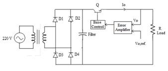
Fig.4.1 Electric circuit diagram of Linear Power Supply
The purpose of the regulator is to maintain Vo at a constant value when the input voltage Vi or the output current or both vary.
The Zener Regulated Power Supply is used for very simple low power applications where the currents involved are very small and the load is permanently
IJSER © 2012
International J o u r n a l o f S c i e n t i f i c a n d E n g i n e e r i n g R e s e a r c h The research paper published by IJSER journal is about Analysis of power Quality in power Supplies
ISSN 2229-5518
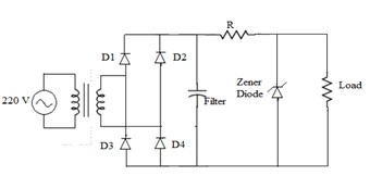
connected across the Zener diode (such as voltage reference or voltage source circuits).The constant reverse voltage Vz of the zener diode makes it a valuable component for the regulation of the output voltage against both variations in the input voltage from an unregulated power supply or variations in the load resistance. To regulate small amounts of current the cheapest approach is to use a Zener Diode.
Fig.4.2 Electric Circuit Diagram of Zener Regulated
Power supply
The figure shows a simple Zener voltage regulator. It operates by way of the Zener diode’s action of maintaining a constant voltage across itself when the current through it is sufficient to take it into the Zener breakdown region. The resistor R1 supplies the Zener current IZ as well as the load current IR2 (R2 is the load). R1 can be calculated as –![]()
Where, VZ is the Zener voltage, and IR2 is the required load current.
The voltage from a half-wave power supply is applied to
a resistor R and a Zener diode connected in series. In normal operation, the Zener diode operates in the "reverse- breakdown" mode, in which the reverse voltage is equal to the nominal Zener voltage and is independent of the current (as long as the current in non-zero). The resistor R helps regulate the current through the Zener diode. As the load current is increased, some of the current that was flowing through the Zener diode is bypassed into the load device, reducing the Zener current, but the voltage remains constant.
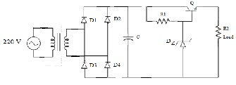
Adding an emitter follower stage to the simple Zener regulator forms a simple series voltage regulator and substantially improves the regulation of the circuit.
Fig.4.3 Electric Circuit Diagram of Series Regulated
Power Supply![]()
![]()
Here, the load current IR2 is supplied by the transistor whose base is now connected to the Zener diode. Thus the transistor's base current (IB) forms the load current for the Zener diode and is much smaller than the current through R2. This regulator is classified as "series" because the regulating element, viz., the transistor, appears in series with the load. R1 sets the Zener current (IZ) and is determined as -![]()
![]()
Where, VZ is the Zener voltage, IB is the transistor's base current and K = 1.2 to 2 (to ensure that R1 is low enough for adequate IB).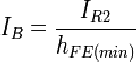
![]()
![]()
Where, IR2 is the required load current and is also the transistor's emitter current (assumed to be equal to the collector current) and hFE(min) is the minimum acceptable DC current gain for the transistor.![]()
This circuit has much better regulation than the simple Zener regulator, since the base current of the transistor forms a very light load on the Zener, thereby minimizing variation in Zener voltage due to variation in the load. Note that the output voltage will always be about 0.65V less than the Zener due to the transistor's VBE drop. Although this circuit has good regulation, it is still sensitive to the load and supply variation. This can be resolved by incorporating negative feedback circuitry into it. This regulator is often used as a "pre-regulator" in more advanced series voltage regulator circuits.
A Switch Mode Power Supply is an electronic power supply that incorporates a switching regulator to convert
IJSER © 2012
International J o u r n a l o f S c i e n t i f i c a n d E n g i n e e r i n g R e s e a r c h The research paper published by IJSER journal is about Analysis of power Quality in power Supplies
ISSN 2229-5518
electrical power efficiently. Like other power supplies, an SMPS transfers power from a source, like mains power, to a load, such as a personal computer, while converting voltage and current characteristics. An SMPS is usually employed to efficiently provide a regulated output voltage, typically at a level different from the input voltage.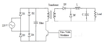
Fig.4.4 Electric Circuit Diagram of Switch Mode Power
Supply
The pass transistor of a switching-mode supply continually switches between low-dissipation, full-on and full-off states, and spends very little time in the high dissipation transitions.
Switch-mode power supplies convert commercial AC power into the required high-frequency DC power using the high-speed switching of semiconductors. Switch- mode power supplies are so compact, light, and efficient that they are used as power supplies by most electronic devices.
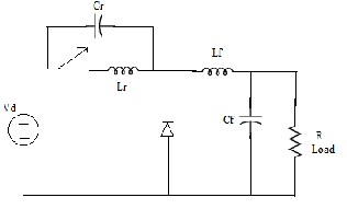
In Zero Current Switching Topology, the switch turns on and turns off at zero current. The peak resonant current flows through the switch but the peak switch voltage remains the same as in its switch mode counterpart. Such a topology is shown in the following figure.
Fig.4.5 Electric Circuit Diagram of Zero Current
Switching Power Supply
Here Lr and Cr are the resonance inductor and capacitor and the Lf and Cf are the filter inductor and capacitor. The inductor Lr limits the di/dt of the switch current, and Lr and Cr constitute a series-resonant circuit. In such converters the current produced by LC resonance flows through the switch, thus causing it to turn on and turn off at zero current [12].
The main function of these converters is to reduce switching losses of the devices (MOSFETs, IGBTs, etc) by operating them either in zero voltage or in zero current switching mode. In the ZCS, the switch is required to conduct a peak current that is higher than the load current Io by an amount Vd//Zo. The turning on and turning off of a switch at a zero current and zero voltage resulting in an essentially lossless switch.
In Zero Voltage Switching Topology, the switch turns on and turns off at zero voltage. The peak resonant voltage flows through the switch but the peak switch current remains the same as in its switch mode counterpart. Such a topology is shown in the following figure.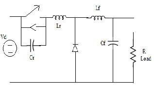
Fig.4.6 Electric Circuit Diagram of Zero Voltage
Switching Power Supply
To achieve ZVS, capacitor Cr is connected in parallel with the switch. With the capacitor, Cr, the internal switch capacitance Cj is added and it affects the resonant frequency only. It is not contributing power dissipation in the switch.
In the zero voltage switching topology, the switch is required to withstand a forward voltage that is higher than Vd by an amount ZoIo. For zero voltage (lossless) turn- on of the switch, the load current Io must be greater than Vd/Zo. With the ZVS, the switching losses in semiconductor devices are zero. The EMI is also reduced during transition. However, the ZVS is preferable for high switching frequencies. The ZVS can also be either of half-wave or full-wave type [12].
IJSER © 2012
International J o u r n a l o f S c i e n t i f i c a n d E n g i n e e r i n g R e s e a r c h The research paper published by IJSER journal is about Analysis of power Quality in power Supplies
ISSN 2229-5518
Simulation was carried out in MATLAB environment using simulink and power system block set (PSB) toolboxes. The simulation results of various types of power supplies has been observed and the power quality parameters namely Total Harmonic Distortion (THD) have been calculated. The results of the following power supplies simulation is as follows:
The simulation of Linear Power Supply has been done in MATLAB software and gets the Total Harmonic Distortion as a result with its Harmonic Spectrum Graph as shown below: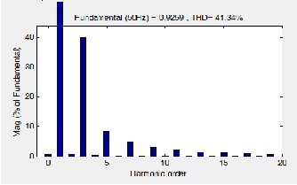
Fig.5.1(a) Harmonic Spectrum of Linear Regulated
Power Supply
The supply current THD are observed to be 70.13 %, which is more than limit specified by IEEE-519.The Ripple content are quite high and the calculate power factor is found to be 0.5.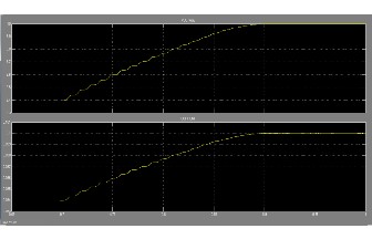
Fig.5.1(b)Output Voltage and Current Waveform of
Linear Regulated Power Supply
The simulation of Zener Regulated Power Supply has been done in MATLAB software and gets the Total Harmonic Distortion as a result with its Harmonic Spectrum Graph as shown below: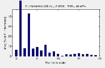
Fig.5.2(a) Harmonic Spectrum of Zener Regulated
Power Supply
The supply current harmonics are observed to be 41.33
%, which is more than limit specified by IEEE-519and the calculate power factor is found to be 0.5 and the ripple content are also high.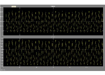
Fig.5.2(b) Output Voltage and Current Waveform of
Zener Regulated Power Supply
IJSER © 2012
International J o u r n a l o f S c i e n t i f i c a n d E n g i n e e r i n g R e s e a r c h The research paper published by IJSER journal is about Analysis of power Quality in power Supplies
ISSN 2229-5518
The simulation of Series Regulated Power Supply has been done in MATLAB software and gets the Total Harmonic Distortion as a result with its Harmonic Spectrum Graph as shown below:
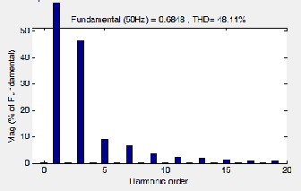
Fig.5.3(a) Harmonic Spectrum of Series Regulated
Power Supply
The supply current harmonics are observed to be
29.62%, which is more than limit specified by IEEE-
519.Ripple content are quite high and power factor measured to be is 0.5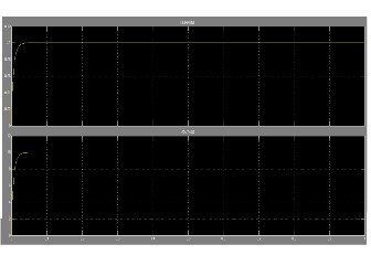
Fig.5.3(b) Output Voltage and Current Waveform of
Series Regulated Power Supply
The simulation of Switch Mode Power Supply has been done in MATLAB software and gets the Total Harmonic
Distortion as a result with its Harmonic Spectrum Graph as shown below: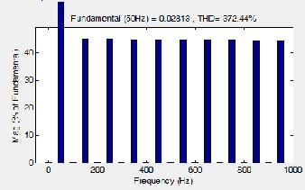
Fig.5.4(a) Harmonic Spectrum of Switch Mode Power
Supply
The supply current harmonics are observed to be
448.41%, which is more than limit specified by IEEE-
519.Ripple content are quite high and the power factor measured to be is 0.5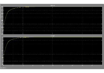
Fig.5.4(b) Output Voltage and Current Waveform of
Switch Mode Power Supply
The simulation of Zero Current Switching Power Supply has been done in MATLAB software and gets the Total Harmonic Distortion as a result with its Harmonic Spectrum Graph as shown below:
IJSER © 2012
International J o u r n a l o f S c i e n t i f i c a n d E n g i n e e r i n g R e s e a r c h The research paper published by IJSER journal is about Analysis of power Quality in power Supplies
ISSN 2229-5518
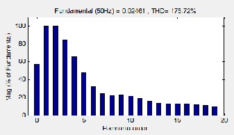
Fig .5.5(a)Harmonic Spectrum of Zero Current Switching
Power Supply
The supply current harmonics are observed to be
55.39%, which is more than limit specified by IEEE-
519.The calculated power factor is obtained to be is 0.5 and The Ripple content are high.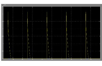
Fig.5.5 (b) Waveform of Power Loss in ZCS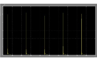
Fig.5.5 (c) Waveform of Reduction of Power Loss With
ZCS Mode
The simulation of Zero Voltage Switching Power Supply has been done in MATLAB software and gets the Total Harmonic Distortion as a result with its Harmonic Spectrum Graph as shown below: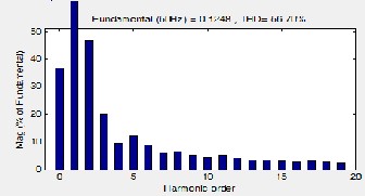
Fig .5.6(a)Harmonic Spectrum of Zero Voltage Switching
Power Supply
The supply current harmonics are observed to be
56.53%, which is more than limit specified by IEEE-
519.Ripple content are high and the power factor measured to be is 0.5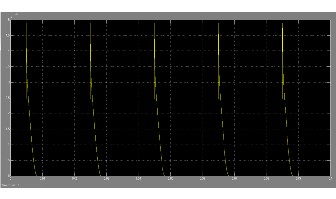
Fig.5.6 (b) Waveform of Power Loss in ZVS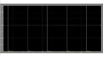
Fig.5.6 (c) Waveform of Reduction of Power Loss With
ZVS Model
IJSER © 2012
International J o u r n a l o f S c i e n t i f i c a n d E n g i n e e r i n g R e s e a r c h The research paper published by IJSER journal is about Analysis of power Quality in power Supplies
ISSN 2229-5518
Power Supplies | THD | Power Factor |
1)Linear Power Supply | 41.34% | 0.8 |
2)Zener Regulated Power Supply | 48.42% | 0.8 |
3)Series Regulated Power Supply | 48.11% | 0.8 |
4)Switch Mode Power Supply | 372.44% | 0.8 |
5)Zero Current Switching Power Supply | 175.72% | 0.8 |
6)Zero Voltage Switching Power Supply | 56.70% | 0.8 |
The simulink is a matlab software package for multi- domain simulation and model -based design of dynamic systems. Since due to the use of power electronic devices, the supply quality is deteriorating day by day, if the supply quality is poor, it may harm the whole system. Hence Matlab/Simulink is a recommended technique before going on to the real time implementation. With this software the user becomes enabling to model, simulate and analyze the most significant signals. Hence, various types of power supplies has been simulated and the related THD and power factor has been calculated which is showing out with the high percentage of harmonic distortion as the power quality issue. Hence, Harmonic Distortion and Power Factor can be improved by using the latest harmonic reduction techniques.
Harmonic distortion is increasing day by day at a faster rate and is a matter of concern to the utility, customer and manufactures of different equipment. To keep the harmonic distortion to low value, following actions are necessary.
1. In India it is necessary first to create awareness regarding harmonic problems, their effects and elimination techniques among the utility, consumers and manufactures of different equipments to make power system less polluted.
2. The harmonic Standards should be imposed on the equipment and should be made mandatory to the manufactures and consumers. The equipment should strictly comply to the harmonic standards before selling it in open market.
3. The utility should monitor the installation of high tension consumers periodically, regarding the harmonic
distortion and penalties should be imposed on
customers using equipments crossing specified limits.
4. Filters should make compulsory to H.T. consumers.
Harmonic currents & voltage distortion are becoming the most severe and complex electrical challenge for the electrical industry. So by designing and giving complete solutions in the form of detuned and tuned harmonic filter systems, Active filters and other protection systems for industrial installation that can ensure the trouble free operation of electrical installation for industries. By defining and implementing these solutions users will be provided with the right quality of power supply for their requirements .
1. ―Power Quality issues standards and guide lines‖,
IEEE, Vol-32, May96
2. IEEE recommended practices and requirements
For harmonic control in electric power system standard
519-1992.
3. P. Lim, T. Wyatt, C. Bray, ―Prevention and Mitigation of Power Quality Concerns Through Education,‖ PRoc. of PCIM/power quality conf.,Dallas, Texas, U.S.A.,September 1994..
4.Task Force on Probabilistic Aspects of Harmonics,
―Time-varying harmonics: Part I—Characterizing measured data,‖ IEEE Trans. Power Del., vol. 13, no. 3, pp. 938–944, Jul. 1998.
5. Task Force on Probabilistic Aspects of Harmonics,
―Time-varying harmonics: Part II—Harmonic summation
and propagation,‖ IEEE Trans.Power Syst., vol. 17, no.
1, pp. 279–285, Jan. 2002.
6. Xiaoyu Wang, Member, IEEE, Jing Yong, Member, IEEE, Wilsun Xu, Fellow, IEEE, and
Walmir Freitas, Member, IEEE, ―Practical Power Quality Charts for Motor Starting Assessment‖ IEEE Transactions on power delivery, vol. 26, no. 2, APRIL
2011.
7. Lei Zhang, Poh Chiang Loh, Member, IEEE, and Feng Gao, Member, IEEE ―An Integrated Nine-Switch Power Conditioner for Power Quality Enhancement and Voltage
IJSER © 2012
International J o u r n a l o f S c i e n t i f i c a n d E n g i n e e r i n g R e s e a r c h The research paper published by IJSER journal is about Analysis of power Quality in power Supplies
ISSN 2229-5518
Sag Mitigation‖ IEEE Transactions on power electronics,
vol. 27, no. 3, pp. 1177, March 2012.
8. Radu Iustin Bojoi, Senior Member, IEEE, Leonardo Rodrigues Limongi, Daniel Roiu, and Alberto Tenconi, Senior Member, IEEE ―Enhanced Power Quality Control Strategy for Single-Phase Inverters in Distributed Generation Systems‖ IEEE Transactions on power electronics, vol. 26, no. 3, pp.798, March 2011.
9. Liu Yingying, Xu Yonghai, Xiao Xiangning, Member, IEEE, Zhu Yongqiang, and Guo
Chunlin ―A Stages Compensation and Control Strategy
for Series Power-Quality Regulator‖ no. 4, pp. 2807
October 2010.
10. Pedro Roncero-Sánchez, Member, IEEE, Enrique Acha, Senior Member, IEEE, Jose Enrique Ortega- Calderon, Member, IEEE, Vicente Feliu, Senior Member, IEEE, and Aurelio Garc-Cerrada, Member, IEEE ―A Versatile Control Scheme for a Dynamic Voltage Restorer for Power-Quality Improvement‖ IEEE Transactions on power delivery vol. 24, no. 1, pp .277
January 2009.
11. Sharad W. Mohod, Member, IEEE, and Mohan V. Aware ―A STATCOM-Control Scheme for Grid Connected Wind Energy System for Power Quality Improvement‖ IEEE systems Journal, vol. 4, no. 3, pp.346, September 2010.
12. John Wiley & Sons, ―Power Electronics: Converters, Applications, and Design‖,by Ned Mohan, Tore M Undeland, Riobbins, 3rd edition, 2009.
IJSER © 2012