International Journal of Scientific & Engineering Research, Volume 4, Issue 7, July-2013 1896
ISSN 2229-5518
1Deepak Makkar, 2Manvir Kaur
—————————— ——————————
In recent years, greater demands have been placed on the transmission network, and this demand will continue to
increase. With the increase in electrical power demand, power systems are becoming complex to operate and at the same time less secure. Such a stressed system is continuously under threat of losing stability following a disturbance [1]. Therefore, it has become more difficult to construct new generation facilities and transmission lines due to energy and environment problems. Hence it is advisable to enhance the power transfer capability of the existing transmission lines instead of constructing new one.
In recent times, the availability of high power semiconductor devices for power system applications have led to technologies such as Flexible AC Transmission Systems (FACTS) for secure loading, power flow control and damping of power system oscillations. The main advantage of the power electronics based FACTS controllers over mechanical controllers is their high speed of operation [2].
Of all the FACTS devices, UPFC has been
recognized as one of the best featured FACTS devices, is capable of providing simultaneous active and reactive power flow control, as well as voltage magnitude control [2]. In the presently used practical implementation, the UPFC consists of two voltage sourced converters (VSC).
————————————————
• 1Deepak Makkar, Thapar University, India, Email: makkardeepak88@gmail.com
• 2Manvir Kaur, Thapar University, India, Email: manvir.kaur@gmail.com
These VSC’s are back-to-back converters, which are connected via a common DC link to allow bi-directional flow of real power between two converters. These two devices are operated from a common DC link provided by a dc storage capacitor [3]. Ratings of this DC link capacitor bank may have a significant impact on the cost and physical size of the UPFC. The capacitor is sized for a specified ripple voltage, typically
10% of the nominal voltage.
This paper presents the detailed model of UPFC installed transmission system. The architecture of the paper in Section 2 describes the structure of UPFC and power system model. In Section 3, the control strategies of UPFC and in Section 4, the simulation results of the SIMULINK transmission model are given. The conclusion is summarized in Section 5.
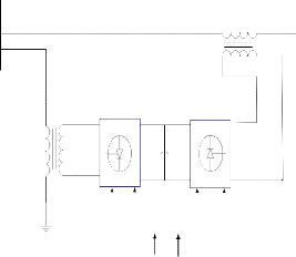
The UPFC is one of the most effective FACTS controller. It provides multifunctional flexibility required to solve many of
the problems facing by power industry and able to control, simultaneously or selectively, all the parameters i.e. voltage, impedance, and phase angle, affecting power flow in the transmission line [3]. The schematic of the UPFC is shown in Fig.1. It consists of two VSC’s connected back-to-back through a DC link capacitor. One of the VSC-1 perform the function of STATCOM by injecting current in the transmission line through transformer (T1) and other VSC-2 performs the function of SSSC by injecting voltage of controllable magnitude and angle in series through a series insertion transformer (T2).
IJSER © 2013 http://www.ijser.org
International Journal of Scientific & Engineering Research, Volume 4, Issue 7, July-2013 1897
ISSN 2229-5518
Vs Vr
Vpq
T2
VSC-1 VSC-2
T1 Vdc
Controller |
Reference Measured
Signal
Signal
Therefore, by injecting a voltage of variable
magnitude and phase angle, the series converter can exchange real and reactive power with the transmission line. No power is absorbed by UPFC in steady state except the power drawn to compensate for the losses.
Thus shunt converter is required to compensate for any real power drawn, supplied by the series converter and the losses. Both the converters can independently exchange reactive power with the system through the connected transformer.
.
The reference real (Pref) and reactive (Qref) power are compared with the measured positive real (Pm) and reactive (Qm) power flowing in the transmission line, and the error of line power is applied to PI controller to derive the desired direct (Vd ) and quadrature (Vq ) component of the series inverter voltage. By using Vd and Vq , the magnitude (Vpq ) and angle (α) of series injected voltage can be calculated as using equation (7) and (8).
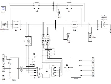
In the study, SimPowerSystem toolbox in MATLAB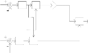
Pm Perror Vdref
alpha
2010 is used to model the 132KV parallel transmission system
with UPFC installed in the middle of one transmission line and other line is uncompensated. The system built with this tool is shown in Fig.2 [4].
Above model consists of two 200 Km long parallel
132KV transmission lines terminated with voltage source
132KV×0.98 with short-circuit power level of 10,000 MVA and X/R ratio=8 with angle difference of 20⁰ between two voltage sources.
The UPFC consists of two voltage source inverters which are connected through a 2000µF common dc capacitor. The complete system parameters are given in Table. 1.
Pref
Qm
Qref
𝑉
PI atan2 K
Gain
Vmag. PI hypot
Vqref
= √(𝑉2 + 𝑉2 ) (7)
SVPWM
Pulses to SSSC
Control part of UPFC includes series converter
𝑝𝑞
𝑑 𝑞
control and shunt converter control. For each part, of which![]()
𝛼 = tan−1 𝑉𝑞
𝑉𝑑
(8)
the series converter controller controls the transmission line
power (real and reactive power), impedance compensation, damp oscillations, whereas the shunt converter controller controls the bus voltage and DC link voltage, to achieve the bus voltage stability and control the power of the line under dynamic conditions.
The series control part strategy shown in Fig. 3, is based on
automatic power flow control mode. The voltage injected by series converter is determined by a closed-loop control system to ensure that the desired active and reactive powers flowing in the transmission line are maintained under disturbances.
Hence, the magnitude (Vpq ) and angle (α) together are used by
the SV-PWM firing pulse generator to generate the desired
pulses for the SSSC voltage source converter.
The shunt part control strategy is shown in Fig.4, is
used to operate the voltage source converter to inject or absorb reactive power to regulate the connecting point voltage to the desired value. The PLL gives the reference angle which is synchronized to the phase A voltage and this reference angle is used to decompose the three phase voltage of STATCOM
IJSER © 2013 http://www.ijser.org
International Journal of Scientific & Engineering Research, Volume 4, Issue 7, July-2013 1898
ISSN 2229-5518
into their real (Vd ) and reactive part (Vq ), via abc to dq0 transformation.
Similarly, the real (Id ) and reactive part (Iq ) of currents can be calculated. This Vd is compared with the desired voltage (V shref ) and error is applied to PI controller to produce the reference reactive
Vdref
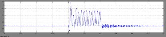
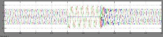
transmission line is highly improved with the presence of UPFC under dynamic condition, whereas real power flow in line without UPFC is decreased. This is also clear that after clearing of fault the oscillations in real power is also damped with the UPFC and system recover its pre-fault conditions faster.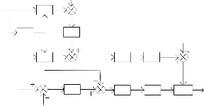
Vabc
abc to Vd
dq0
Iabc
PLL
abc to dq0
PI 1
Iqref
Iq
PI 3
Id
Vq
atan2
theta alpha
Vdcref
PI 2
Idref
Vd
PI 4
hypot
Vmag
SV PWM
Pulses to
Vdcm
STATCOM
current (Iqref). The reference real current (Idref) can be calculated by comparing reference DC voltage (Vdcref ) with measured DC capacitor voltage (Vdcm) and the error is passed through a PI controller. After comparing the reference and measured values of real (Idref) and reactive current (Iqref), the error is passed through a PI controller to obtain real (Vd) and reactive (Vq) voltage magnitude. These voltages are used to calculate Vpq and angle (Ɵ1). This voltage magnitude and angle are fed to SV-PWM firing pulse generator to generate the desired pulses for the STATCOM.
The two machine test system, which is simulated by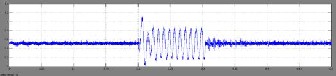
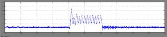
MATLAB/SIMULINK with parameters as given in Table 1. The inverters consist of IGBT based three phase voltage source converters. As discussed earlier, the UPFC can control line voltage, real and reactive power of transmission line in steady state and dynamic conditions. The disturbance used is a single-phase fault near bus 2 and bus 4 of compensated and uncompensated line respectively, at time t = 0.3 second, and cleared in 0.10 second (i.e. at t=0.4). The receiving and sending end voltages are 1p.u. The simulation results for real, reactive power, voltage and current are discussed below: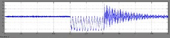
power flow in compensated and uncompensated transmission line respectively. Transmission of real power in existing
the transmission line with and without UPFC is shown in
Fig.6.1 and Fig.6.2 respectively. It is cleared from figures that the UPFC employed line can be easily control the rise in reactive power by absorbing this excess power and improve the efficiency of transmission line. Similarly, as in real power flow control, the oscillations are also damped for reactive power.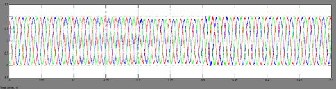
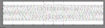
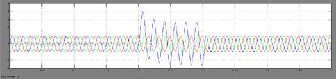
current in the line is raised to
IJSER © 2013 http://www.ijser.org
International Journal of Scientific & Engineering Research, Volume 4, Issue 7, July-2013 1899
ISSN 2229-5518
presents an improvement in the real and reactive power flow through transmission line with UPFC when compared to the system without UPFC.
dangerous level. Fig.8.1 and Fig.8.2 shows the current in the
line with UPFC and without UPFC respectively. The results show that with the use of UPFC the rise in current is suppressed to safe value. This increase the system security and safety under steady state and dynamic conditions.
In this study, the MATLAB/SIMULINK
environment is used to simulate the model of UPFC to a three phase-three wire transmission system. This paper presents control and performance of UPFC on a transmission line. A control system is simulated with shunt converter in voltage control mode and series converter in power flow control mode. Simulation results show the response of UPFC in controlling real and reactive power through the line. Due to shunt converter, bus voltage regulation is improved. The simulation result shows the fast response and effectiveness of the presented control scheme using PI controller. This paper
1. S. Tiwari, R. Naresh, R. Jha, “Neural network
predictive control of UPFC for improving transient stability performance of power system”, Applied Soft Computing, Volume 11, Issue 8, December 2011, Pages 4581-4590, ISSN 1568-4946.
2. B. Geethalakshmi, P. Dananjayan, “Investigation of performance of UPFC without DC link capacitor”, Electric Power Systems Research, Volume 78, Issue
4, April 2008, Pages 736-746, ISSN 0378-7796.
3. N.G. Hingorani, “FACTS-Concepts and Technology
of Flexible AC Transmission Systems” IEEE Power Engineering Society, (standard publishers, IEEE press, 2001).
4. X. Zhou, H. Wang, “ Performance Evaluation of a Distance Relay as applied to a Transmission System with UPFC”, IEEE Transaction on Power Delivery, Vol. 21, No.3,July 2006
5. E. Gholipur, S. Saadate, “Improving of Transient Stability of Power Systems Using UPFC”, IEEE Trans. On Power Delivery, Vol.20, No. 2, April 2005
6. Z. Huang, Y. Ni, “Application of Unified power
Flow Controller in Interconnected Power Systems- Modelling, Interface,Control Strategy, and Case Study”, IEEE Trans. On Power Systems, Vol.15, No.
2, May 2000.
7. H. Liu; H. Zhu; Y. Li; Y. Ni, "Including UPFC dynamic phasor model into transient stability program," Power Engineering Society General Meeting, 2005. IEEE , vol., no., pp.302,307 Vol. 1,
12-16 June 2005.
8. Y. Shu-jun, S. Xiao-yan, W. Yan; Y. Yu-Xin, Y. Zhi, "Research on dynamic characteristics of Unified Power Flow Controller (UPFC)," Electric Utility Deregulation and Restructuring and Power Technologies (DRPT), 2011 4th International Conference on , vol., no., pp.490,493, 6-9 July 2011
9. KK. Sen., E.J. Stacey, "UPFC-unified power flow controller: theory, modeling, and applications," Power Delivery, IEEE Transactions on, vol.13, no.4, pp.1453,1460, Oct 1998.
10. S. Zheng, Yoke-Lin Tan, S. Cheng; Y. Zhu, "Dynamic characteristic study of UPFC based on a detailed simulation model," Power Engineering Society Winter Meeting, 2000. IEEE, vol.2, no., pp.1360, 1364 vol.2, 2000.
IJSER © 2013 http://www.ijser.org