International Journal of Scientific & Engineering Research Volume 3, Issue 6, June-2012 1
ISSN 2229-5518
Analysis and Design of steel framed buildings with and without Steel Plate Shear Walls
Ms Deepika C. Hiwrale 1, Prof. P.S. Pajgade 2
ABSTRACT
The present paper describes the analysis and design of high-rise steel building frame with and without Steel plate shear wall (SPSW ). For present work equivalent static analysis is carried out for steel moment resisting building frame having (G+6) storey situ ated in zone III. Modelling will be done by using strip modelling. The analysis of steel plate shear wall and the building are carried out using Software STAAD PRO V8i SELECT series II. The main parameters consider in this paper to compare the seismic performance of buildings are bending moment, shear force, deflection and axial force. The models are analyze by equivalent static analysis as per IS 1893:2002 and design will be carried out
by using IS 800-2007.
Keywords—
Steel plate shear wall ( SPSW ) , steel building, strip model, IS 800-2007 , IS 1893-2002, seismic coefficient method, tension
field action, seismic design, boundary element.
—————————— ——————————
1. 1 INTRODUCTION
As compare to the Reinforced cement concrete (RCC) the steel has got some important physical properties like the high strength per unit weight and ductility [3]. The high yield and ultimate strength result in slender sections. Being ductile the steel structures give sufficient advance warning before failure by way of excessive deformations. These properties of steel are of very much vital in case of the seismic resistant design. Steel shear wall is a lateral load resisting system consisting of vertical steel plate infills connected to the surrounding beams and columns and installed in one or more bays along the full height of the structure to form a cantilever wall. Shear walls are vertical elements of the horizontal force resisting system. The main role of steel shear wall is to collect lateral forces of earthquake in a building and transfer those forces to the foundation. The web plates in steel shear walls are categorized according to their ability to resist buckling.
————————————————
1 Final Year Student (M.E. Structure) , 2 Professor
Department Of Civil Engineering
Prof. Ram Meghe Institute of Technology & Research
Badnera, Amravati-444701, Maharashtra, India
Email ID: deepikahiwrale@gmail.com
Email ID: ppajgade@gmail.com
The web plates can be sufficiently stiffened to preclude buckling and allow the full shear strength of the web to be reached. The steel plate shear walls are mainly used in multistoried building in the foreign countries such America, Japan, Canada etc.
1.2 PURPOSE OF SPSW
Shear walls are not only designed to resist gravity
/ vertical loads (due to its self-weight and other living / moving loads), but they are also designed for lateral loads of earthquakes / wind. the walls are structurally integrated with roofs / floors (diaphragms) and other lateral walls running across at right angles, thereby giving the three dimensional stability for the building structures. Shear wall structural systems are more stable. Because, their supporting area (total cross-sectional area of all shear walls) with reference to total plans area of building, is comparatively more, unlike in the case of RCC framed structures.
![]() Walls have to resist the uplift forces caused by the pull of the wind.
Walls have to resist the uplift forces caused by the pull of the wind.
![]() Walls have to resist the shear forces that try to push the walls over.
Walls have to resist the shear forces that try to push the walls over.
![]() Walls have to resist the lateral force of the wind
Walls have to resist the lateral force of the wind
that tries to push the walls in and pull them away from the building.
IJSER © 2012 http://www.ijser.org
International Journal of Scientific & Engineering Research Volume 3, Issue 6, June-2012 2
ISSN 2229-5518
2. MODELING OF STEEL PLATE SHEAR WALLS
2.1 Strip Modeling
This is the most popular way of modeling thin, non- compact shear walls. It is purely based on the diagonal tension field action developed immediately after the buckling of the plate. This type of modeling is recommended by the code of Canada, the CAN/CSA-S16-01 in the analysis and design procedure of the SPSWs. In the analysis software the steel plate in the wall panel is to be replaced by a series of truss members (struts ) or the strips along the tension field. There are two ways of modeling by this method. The first one is the strips inclined at uniform angle with the horizontal and the other is the multi-strip model as shown in the following figures.
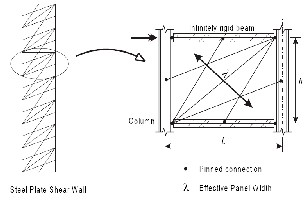
The two models of the SPSWs are as shown in the following figures. The first one was proposed by Thorborn. The second, Multi-angle strip model was proposed by Rezaii.[9]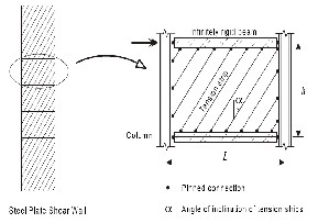
Figure 2.1.1 Strip Model Representation of a SPSW
2.2 Modeling guide lines for Strip Model
![]() A minimum of ten strips are to be provided per wall panel.
A minimum of ten strips are to be provided per wall panel.
![]() Each strip is pinned at both of its ends to the
Each strip is pinned at both of its ends to the
surrounding beams or columns as per its location in the wall panel.
![]() Each strip has the width equal to the centre to centre spacing of the consecutive strips.
Each strip has the width equal to the centre to centre spacing of the consecutive strips.
![]() thickness of the strips is kept same as that of the plate.
thickness of the strips is kept same as that of the plate.
![]() The strips are normally inclined at 45 degree with
The strips are normally inclined at 45 degree with
the horizontal. The angle of inclination shall be in the range of 38 to 45 degrees with the horizontal. Slight variation in the angle does not affect the behaviour of the model.
![]() The connection of the beams of that panel with the
The connection of the beams of that panel with the
columns shall be kept pinned or hinged.
The researchers who have worked in this area have thus suggested two strip models as shown in the figures. In the first the strips are inclined diagonally at an uniform angle, generally at 450 with the horizontal. The other is the multi- angle strip model in which the strips are inclined at different angles.
3. METHODS OF ANALYSIS
There are a number of methods by which the buildings with the steel shear walls can be analysed.
The thin steel shear walls modeled using the strip model, one has to use the equivalent static method also called as Seismic coefficient method only. This is because of the fact that the tension struts in the strut model are effective only when they are oriented in such a way that they carry axial tension. As the SPSWs are modeled here by using the popular tension-strip model also called as strip model,the method of analysis used is the seismic coefficient
method as specified by the IS 1893 (Part I ) : 2002.
Figure 2.1.2 Multi-angle strip model of a SPSW
3.1 Seismic Analysis Using IS 1893 (Part 1): 2002
IJSER © 2012 http://www.ijser.org
International Journal of Scientific & Engineering Research Volume 3, Issue 6, June-2012 3
ISSN 2229-5518
3.1.1 Static Analysis
Load factors![]()
α = tan 1
In the design of steel structure, following load
combinations as given in the IS 1893 (Part1): 2002 and IS
800-2007 are:
1.5 DL+1.5 LL+ 1.5RLL
1.2 DL+0.6 LL+1.2 EL
1.2 DL+0.6 LL-1.2 EL
1.5 DL+1.5 EL
1.5 DL-1.5 EL
Where,
t = Thickness of web plate
L = distance between VBE centerline
Ac = cross- sectional area of a VBE
h = distance between HBE centerline
Ab = cross- sectional area of a HBE
Ic = moment of inertia of a VBE taken
perpendicular to the direction of the web plate line
0.9 DL+1.5 EL
0.9 DL-1.5 EL
4. DESIGN OF STEEL BUILDING WITH AND WITHOUT STEEL PLATE SHEAR WALL
4.1 DESIGN OF STEEL BUILDING WITH STEEL PLATE SHEAR WALL
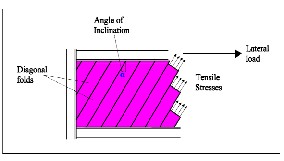
Fig. 4.1 Idealized tension- field action in a typical SPW
4.1.1 Thickness of steel panel
![]()
twi =
4.1.3 DESIGN OF VERTICAL BOUNDARY ELEMENT
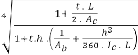
For vertical boundary elements (VBE), it has been recommende that the moment of inertia Ic should be such that [9 ] :
0.70 h ![]() ≤ 2.5
≤ 2.5
Ic ≥ ![]()
Design Strength of Tension member as per the IS 800-2007 cl. 6.2 [12]
![]()
![]()
Where ,
i the i-th story
Vi is the storey shear
L is the bay width
Fy is the material yield stress
where,
fy = yield stress of material
Ag = gross area of cross – secti
Ƴ mo = partial safety factor for failure in tension
By yielding
4.2 DESIGN OF STEEL BUILDING WITHOUT
STEEL PLATE SHEAR WALL
IJSER © 2012 http://www.ijser.org
International Journal of Scientific & Engineering Research Volume 3, Issue 6, June-2012 4
ISSN 2229-5518
Design of steel building without SPSWs carried out as per the specification given in IS 800- 2007 by using design software Staad pro V8i SELECT SERIES 2. [20]
5.1 ANALYSIS PROBLEM
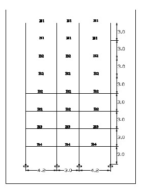
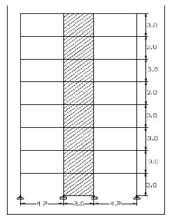
5.2 .2 Elevation of a G+6 story Steel building
5.2 STRUCTURAL DETAILS :-
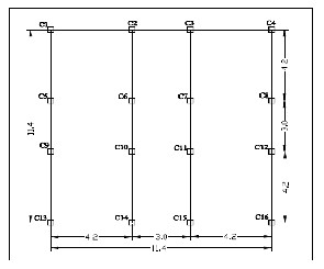
5.2 .1 Plan of a G+6 story Steel buildi
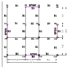
5.2.3 Plan of a G+6 story Steel building with SPSW
IJSER © 2012 http://www.ijser.org
International Journal of Scientific & Engineering Research Volume 3, Issue 6, June-2012 5
ISSN 2229-5518
For SPSWs Building:
Size of Beam :
B1 = ISWB 300
B2 = ISHB 200
B3 = ISWB 150
Size of Column :
1 ) FOR C1 , C4 , C13 , C16
TUBE 270 X 270 X 6
TUBE 270 X 270 X 8
5.2.4 Elevation of a G+6 story Steel building with SPSW
5.3 Member Specification: For Steel building :
2 ) FOR C2 , C3 , C5 , C9 , C8 , C12 , C14 , 15
TUBE 270 X 270 X 8
TUBE 270 X 270 X 10
TUBE 270 X 270 X 12
3 ) FOR C6 , C7 , C10 , C11
TUBE 270 X 270 X 8
TUBE 270 X 270 X 10
Size of Beam :
Size of Column :
B1 = ISHB 225
B2 = ISWB 350
B3 = ISHB 300H
B4 = ISHB 400
The above mentioned both the frame has been analysed and Design by using STAAD-PRO V8i SELECT SERIES 2 software. For getting results some column has been selected and they are as column nos. 1 ,7 & 9. The
1 ) FOR C1 , C4 , C13 , C16
TUBE 330 X 330 X 8
TUBE 330 X 330 X 10
TUBE 330 X 330 X 16
2 ) FOR C2 , C3 , C5 , C9 , C8 , C12 , C14 , 15
TUBE 330 X 330 X 16
TUBE 330 X 330 X 12
TUBE 330 X 330 X 10
TUBE 330 X 330 X 8
3 ) FOR C6 , C7 , C10 , C11
TUBE 330 X 330 X 20
TUBE 330 X 330 X 16
TUBE 330 X 330 X 12
TUBE 330 X 330 X 10
TUBE 330 X 330 X 8
results found to be are shown with the help of graph for the
parameters.
IJSER © 2012 http://www.ijser.org
International Journal of Scientific & Engineering Research Volume 3, Issue 6, June-2012 6
ISSN 2229-5518
6.1 COMPARISON OF RESULTS
6.1.1 DEFLECTION RESULT
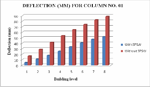
Figure:1 Deflection in (mm) for Column No. 01
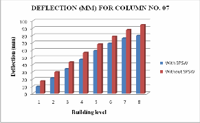
Figure: 2 Deflection in (mm) for Column No. 07
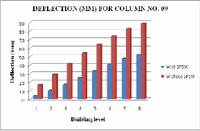
Figure: 3 Deflection in (mm) for Column No. 09
IJSER © 2012 http://www.ijser.org
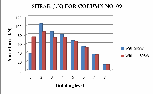
6.1.2 SHEAR FORCE RESULT
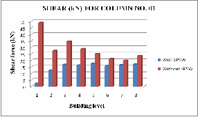
Figure: 4 Shear Force in (kN) for Column No. 01
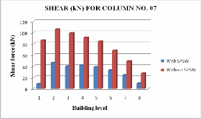
Figure: 5 Shear Force in (kN) for Column No. 07
International Journal of Scientific & Engineering Research Volume 3, Issue 6, June-2012 7
ISSN 2229-5518
Figure: 6 Shear Force in (kN) for Column No. 09
6.1.3 BENDING MOMENT RESULT
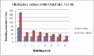
Figure: 7 Bending moment in (kNm) for Column No. 01
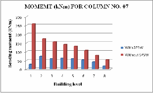
Figure: 8 Bending moment in (kNm) for Column No. 07
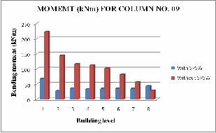
Figure: 9 Bending moment in( kNm) for Column No. 09
4.1.4 AXIAL FORCE RESULT
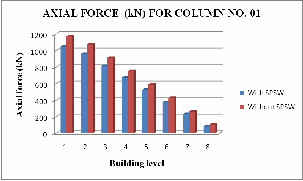
Figure: 10 Axial Force in ( kN) for Column No. 01
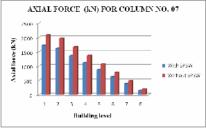
Figure: 11 Axial Force in ( kN) for Column No. 07
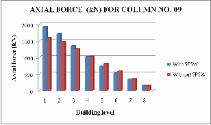
Figure: 12 Axial Force in ( kN) for Column No. 09
IJSER © 2012 http://www.ijser.org
International Journal of Scientific & Engineering Research Volume 3, Issue 6, June-2012 8
ISSN 2229-5518
REFERENCE
1. Thorburn J.L., Kulak G.L., and Montgomery C.J. (1983). “Analysis of steel plate shear walls”, Structural Engineering Report No.107, Department of Civil Engineering, The University of Alberta
Edmonton, Alberta, pp 1-167.
6.1.4 WEIGHT OF STEEL RESULT
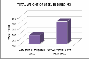
Figure: 13 Total weight of steel in ( kN)
1)Results indicate that steel plate shear walls have a large effect on the behavior of frames under earthquake excitation. In general, infill steel plate increase stiffness of the structure.
2) Deflection in case of without SPSW is very large & in case of with SPSW deflection is very less.
3) With the use of steel shear walls in the buildings, the bending moments in the column are reduce.
4) From fig. 13, due to presence of SPSW total weight of steel in building is reduced than building without SPSWs.
5) From above result it is observed that, due to use of SPSW in building there is considerable decrease in value of bending moment, shear force, deflection and axial force for some columns and also quantity of steel is reduced. Hence steel building with SPSWs is economical compare to without SPSWs.
6) Due to relatively small thickness of SPSW compared to reinforced concrete shear walls, from architectural point of view, steel shear wall occupy much less space than equivalent
reinforced concrete shear wall .
2. Mayank K. Gupta1, Swapnil B. Kharmale2 and Siddhartha Ghosh3 . “DUCTILITY-BASE SEISMIC DESIGN OF STEEL PLATE SHEAR WALLS: PRACTICAL APPLICATION USING STANDARD SECTIONS “,Department of Civil Engineering, Indian Institute of Technology Bombay, Mumbai, India , pp 93 –
98.
3. Londhe R.S. and Chavan. A. P. (2010). “Behavior of building frames with steel plate shear wall”. Asian Journal of Civil Engineering (building and housing) vol. 11, no. 1 pages 95-102.
4. Ghosh Siddhartha, Farooq Adam, Das Anirudha (2009). “Design
of steel plate shear walls considering inelastic drift demand”.
Journal of Constructional Steel Research 65. pp 1431_1437.
5. Berman Jeffrey and Bruneau Michel (November 2003). “Plastic Analysis and Design of Steel Plate Shear Walls.” Journal of Structural Engineering © ASCE.
6. Jeffrey Berman ,” Plastic Analysis and Design of Steel Plate Shear Walls.” Department of Civil, Structural & Environmental Engineering, University at Buffalo. Pp 36-39.
7. A. DEYLAMIa, J. ROWGHANI-KASHANIb ,” Analysis and Design of Steel Plate Shear Walls using orthotropic membrane model .” The Twelfth East Asia-Pacific Conference on Structural Engineering and Construction . pp 3339 – 3345.
8. Mahmoud REZAI, Carlos E VENTURA And Helmut G L PRION
,” NUMERICAL INVESTIGATION OF THIN UNSTIFFENED STEEL PLATE SHEAR WALLS “,12th World Conference on Earthquake Engineering 2000 pp 1-4
9. MICHEL BRUNEAU, P.E., JEFF BERMAN, DIEGO LOPEZ GARCIA, AND DARREN VIAN,” STEEL PLATE SHEAR WALL BUILDINGS: DESIGN REQUIREMENTS AND RESEARCH “,Post-Doctoral Research Associate, Department of Civil,
Structural, and Environmental Engineering, University at Buffalo, Buffalo, NY 14260. Pp 1-3
10. . Sabelli, R. and Bruneau, M. (2007), “Design Guide 20: Steel Plate Shear Walls”American Institute of Steel Construction, Chicago, IL, USA.
11. IS 1893 (Part 1):2002, Indian Standard, “CRITERIA FOR
EARTHQUAKE RESISTANT DESIGN OF STRUCTURES”, PART
1 GENERAL PROVISIONS AND BUILDINGS.(Fifth Revision).
12. IS 800:2007, Code of practice for general construction in steel, BUREAU OF INDIAN STANDARDS, NEW DELHI.
IJSER © 2012 http://www.ijser.org
International Journal of Scientific & Engineering Research Volume 3, Issue 6, June-2012 9
ISSN 2229-5518
IJSER ©2012
htt p:llwww .llser. ora