—————————— ——————————
International Journal of Scientific & Engineering Research, Volume 5, Issue 3, March-2014 293
ISSN 2229-5518
An Improved Satellite Digital TV
Broadcasting Layout based On the
Compression Model with Proposed QPSK
model
Salauddin Mahmud
Abstract:-Digital Video Broadcasting – Satellite (DVB-S), - Second Generation (DVB-S2) is a digital television broadcast standard that has been designed as a successor for the popular DVB-S system. In this paper Satellite television system Digital Video Broadcasting layout has been improved. Data compression model has been inserted to the broadcasting layout and also Proposed QPSK modulation has been design based on the data compression model.
Index Terms—Proposed QPSK, Digital Broadcasting Layout, Data Compression Model, H.264 Codec, Original bit, Modified bit.

—————————— ——————————
Digital Satellite television is television encoding delivered by the means of communications satellite and received by an outdoor antenna. In this paper the digital satellite television system layout has been improved. From the block diagram TV signal comes from several signal sources like camera, VTR, Studio or live feed. Now the several signals are fed to the several H.264 encoders. Multiplexer takes the several input from the encoders and give the single line output. This output acts as an input of the Proposed Compression Model. This compression model compresses half of its input signal. The compressed signal is fed to the Proposed QPSK modulator. Because the traditional modulation is not able to handle this kind of signal. The output of the Proposed QPSK modulation is analog. Now the frequency up converter adds the carrier signal with the analog signal. High power amplifier amplifies the power of the signal. Antenna transmits the amplified signal to the satellite.
Fig 1: Modified Satellite Digital TV Broadcasting Layout
The proposed technique is shown that, the data bits can be represented by of its half bits. That means 128 bit
IJSER © 2014 http://www.ijser.org

International Journal of Scientific & Engineering Research, Volume 5, Issue 3, March-2014 294
ISSN 2229-5518
can be represented by 64 bits, 64 bit can be represented by 32 bits, and 32 bits can be represented by 16 bits. According this rule it could be said that 1GB data can be represented by 512 MB data.
This technique is based on the logical truth table,
A | B | Z |
0 | 0 | 0 |
0 | 1 |
|
1 | 0 |
|
1 | 1 | 1 |
Table 1: Truth table of proposed technique
Resultant output is 0 when two input bits are 0 and 0. Resultant output is 1 when two input bits are 1 and 1. Resultant output is ![]() when two input bits are 0 and 1. Resultant output is
when two input bits are 0 and 1. Resultant output is ![]() when two input bits are 1 and 0.
when two input bits are 1 and 0.

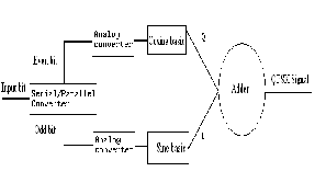
Fig 2: Conventional QPSK Block diagram
In Quadrature Phase Shift Keying (QPSK) two sinusoids (sin and cos) are taken as basic functions for modulation. Modulation is defined by the changeable phase of the basic functions depending on the message signs. In QPSK, modulation is symbol based, where one symbol contains 2 bits.
Fig 3: Constellation diagram of conventional QPSK
The constellation diagram of QPSK will show the constellation points lying on both x and y axis. This means that the QPSK modulated signal will have an in- phase component (I) and also a quadrature component (Q). This is because it has only two basic functions.
A QPSK modulator can be implemented as follows. A serial to parallel converter is used to separate odd and even bits from the bit stream. Each of the odd bits (quadrature component) and even bits (in-phase component) are converted to analog in parallel. The signal on the in-phase component is multiplied by cosine component and the signal on the quadrature component is multiplied by sine component. QPSK modulated signal is generated by adding the signal from both in-phase and quadrature division.
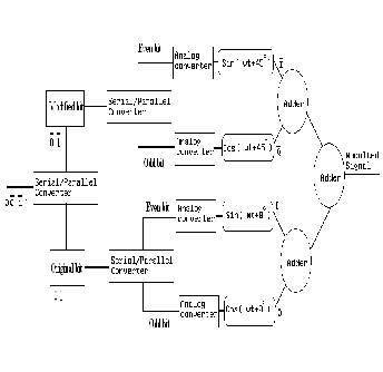
Fig 4: Proposed QPSK Block diagram
From Compression model, Data are divided into two parts. One is original digital bit another is modified
IJSER © 2014 http://www.ijser.org
International Journal of Scientific & Engineering Research, Volume 5, Issue 3, March-2014 295
ISSN 2229-5518
digital bit. 0 and 1 are original digital bits. ![]() and
and ![]() are modified digital bits. But these modified bits cannot be handled by the traditional modulator like QPSK. That is why traditional modulator will have to be modified.
are modified digital bits. But these modified bits cannot be handled by the traditional modulator like QPSK. That is why traditional modulator will have to be modified.
Bit stream are mixed with original bit and modified bit. These data stream fed to the serial to parallel converter. Now original bit and modified bit are separated. Now the modified bit and original bits are parallel fed to the Serial to parallel converter. Upper portion is even bit and lower portion is odd bit.
Part 1: Data can be handling by this modulator. Modified data are fed to the serial to parallel converter. Now even data and odd data are separated. Even and odd data are converted into analog signal. Even analog data are fed to the analog oscillator sin (ωt+45°) and odd analog data are fed to the cos (ωt+45°). Adding two signal we can get analog signal.
Part 2: Similarly original data are fed to the serial to parallel converter. Now even data and odd data are separated. Even and odd data are converted into analog signal. Even analog data are fed to the analog oscillator sin (ωt+0°) and odd analog data can fed to the cos (ωt+0°). Adding two signal we can get analog
signal.
Now adding part 1’s and Part 2’s output signal and get the ultimate analog output signal or modulated signal.
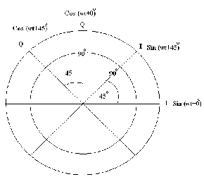
Fig 4: Constellation diagram of Proposed QPSK
![]()
The constellation diagram of Proposed QPSK will show the constellation points lying on both x and y axis. This means that the Modified QPSK modulated signal will have two in-phase components (I) and ( ) and also
two quadrature component (Q) and ( ). This is![]()
because it has four basic functions. The different between (I) and ( ) is 45°. Similarly the different between (Q) and ( ) is also 45°. And the difference between (I) and (![]() ), (Q) and (
), (Q) and (![]() ) are 90°.
) are 90°.
Part 1:
Sin(ωt + 45°) +Cos (ωt +45°) = ![]() Cos(ωt + 0°)
Cos(ωt + 0°)
Part 2:
Sin (ωt + 0°) +Cos (ωt+ 0°) = ![]() Cos (ωt - 45°) Output Signal:
Cos (ωt - 45°) Output Signal:
Sin (ωt + 0°) +Cos (ωt + 0°) + Sin (ωt + 45°) +Cos (ωt +
45°) = 2.61312 Cos (ωt - 22.5°)![]()
2.61312 Cos (ωt - 22.5°) this analog signal contains
Or 00011011
Conventional QPSK modulation contains 2 bits per symbol. In the block diagram it is seen that the output signal of Proposed QPSK modulation contain 8 bits per signal.
Now a day’s digital satellite television provides high quality video broadcasting. For this it needs large bandwidth. This Proposed model will give facilities to deliver video broadcasting in low bandwidth.
[1] Salauddin Mahmud, “An Improved Data Compression Method for General Data”, International Journal of Scientific and Engineering Research Vol-3, Issue-3, March-2012.
IJSER © 2014 http://www.ijser.org
International Journal of Scientific & Engineering Research, Volume 5, Issue 3, March-2014
ISSN 2229-5518
Salauddin Mahmud is doing M.Sc. in Computer Science and Engineering from Daffodil International University, Bangladesh. PH: +8801672463556. (E-mail: raju_681@yahoo.com)
296
IJSER IS)2014