International Journal of Scientific & Engineering Research, Volume 5, Issue 12, December-2014 928
ISSN 2229-5518
Alternating Current Voltage Stabilizer by Using
Pulse Width Modulation
O.M.Butt, S.M.H.Gillani, M. Ahmed, A.N. Aslam, H.T.Mustafa
Transistor (Mosfet), Buck-Boost Transformer, PIC Microcontroller, Zener diode, Analog Signal
—————————— ——————————
C Voltage stabilizer and regulator is a system which maintains a constant supply of ac voltage across the load.
Commonly, it is based on three different configurations: buck (step-down), boost (step-up) or buck boost. The type of con- figuration depends upon the requirement.
Typically an electromagnetic voltage stabilizer is a combina- tion of two parts, electrical and mechanical. Electrical part drives the mechanical part to produce an appropriate output. Normally this mechanical part consists of servo motor and relay which changes the tapings of the transformer to stabilize the ac output voltage [1]. Moving parts of the servo motor and relay results in wear and tear. Due to this mechanical move- ment response time could not compensate rapidly the fluctua- tions in voltage. Despite of this stumpy correction speed there will be voltage overshoot and voltage drop. These drawbacks result a poor voltage regulation and reduces the efficiency and reliability.
In order to reduce these effects electronic circuit is introduced based on some semiconductor or power switching devices which substitute these moving mechanical parts. The power device which is proposed in this paper is power MOSFET IRF-
840. This power MOSFET generates an appropriate Pulse Width Modulation in accordance with the input which drives the transformer to stabilize the output ac voltage.
This Pulse Width Modulation buck (subtract) or boost (add) in the main voltage. This serially changes the secondary voltage of buck-boost transformer and it results in a stabilized output voltage available [2].
————————————————
• O M Butt is currently pursuing undergraduate degree in Electrical Engi- neering program at University of the Punjab, Lahore-Pakistan.
E-mail: osamabutt26@ymail.com
• S M H Gillani and M Ahmed are currently pursuing undergraduate degree in Electrical Engineering program at University of the Punjab, Lahore- Pa-
kistan.
• A N Aslam is currently assistant professor in Electrical Engineering De-
partment at University of the Punjab,Lahore- Pakistan
• H T Mustafa is currently lecturer in Electrical Engineering Department at
University of the Punjab,Lahore- Pakistan
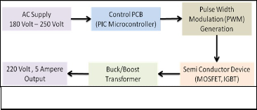
Block Diagram of Propsed Technique
Figure 3
The design is mainly based on two main sections i-e “Control- ler Section” and “Buck-Boost Section”. This proposed design is more efficient, reliable and stable. This technique is very much improves in its operation and performance as compared to conventional one.
In novel design, there is no mechanical moving part, therefore it enhances its hardware life and also it needs negligible maintenance as there is no wear and tear. This design com- pensate the voltage more rapidly than old electromechanical design, as in that conventional design some mechanical switches like relay or servo motor are used to change the tap- ings of transformer to compensate the voltage. This mechani- cal process need time and eventually could not compensate rapid surges and spikes. But this new design uses power switch device (power MOSFET IRF840) which has switching time of 0.106 ms [3]. Hence it could increases the efficiency up till 90%. A prominent advantage of this novel configuration is its size and its suitability for heavy loads. Conventional elec- tromechanical stabilizer becomes bigger, inefficient and une- conomical as ac load increases to kilo-volt ampere. But this new design could handle heavy loads more efficiently, eco- nomically and effectively.
This section is based on an electronic circuit consisted on mi- cro-controller [4]. In this proposed topology PIC16F877A is used for above purpose. PIC microcontroller is the most ap- propriate for the design because it has many built in features related to the solution of the problem stated above. It can tol-
IJSER © 2014 http://www.ijser.org
International Journal of Scientific & Engineering Research, Volume 5, Issue 12, December-2014 929
ISSN 2229-5518
erate noise created by the analog signal of the input alternat- ing current(ac supply), has built in analog to digital conver- tor(A/D convertor) and most importantly it has built in PWM (Pulse Width Modulation) module[5],[6].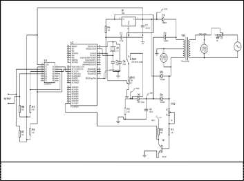
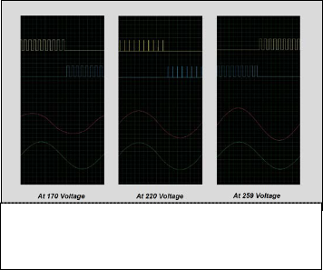
Yellow, Blue = Pulse Width Modulation Train
Red = Input Ac Voltage r
Green = Output
Figure 3 d
Figure 1
An analog signal will be fed at port ‘A’ pin 2 of the controller from the transformer. Here ADC (Analog to Digital Convert- er) converts this analog signal to digital and measures its level according to a reference value. A proportional voltage to the main is supplied from the transformer.
This proportional voltage varies as the main voltage changes. This variation could be calculated by following manner:
For 220 volts main, a 9 volt step down transformer and 10 volt zener diode is used.
Output at control = 9![]() = 12.7 volts
= 12.7 volts
Voltage supplied to ADC pin = 12.7 – 10 = 2.7 volts
Similarly it will be 5 volt for a rise in 259 voltage in main and
drop to zero for 172 voltages. In this way ADC will obtain a
range of the fluctuation of ac voltages in mains and measure the compensation. According to voltage level measurement, PIC16F877A generates PWM (Pulse Width Modulation) at pin
16 & 17. This PWM add (boost) or subtract (buck) sine voltage in the main to keep a constant level of ac voltage across the load which is actually the desired objective.
at port D which produces a rectangular pulse from the half- wave rectified low voltage (9V) from the transformer (9V-0-
9V). Frequency of 50Hz from main source will be used as ref- erence for positive and negative half cycles. This will pro- duce the pulses at A and B points in turn. These pulses which change in their width and are therefore called pulse width modulation.
During the initialization of PIC16F877A, port A is set as input, and port B and port C is set for output. Port B will display main AC voltage which is to be stabilized. Pin 16 and 17 of port C will be used to feed pulse width modulation to the power Mosfet IRF 840 [4]. Intially, highest value of period is set, than pre-scaler and post-scaler values are set to ‘1’ [6].
After initializing, timer is set to be ‘on’ and analog signal is received at port A. Here analog to digital converter digitalize this receiving signal by using ‘Vss ’ and Vdd ’ as reference [5]. Then this digitalized data is compared and change the duty cycle of PWM which is receiving as output from port C. Then this PWM is algebraically added in disturbed input. When the output voltage becomes stabilized, controller will wait in this state until an interrupt or change in the input voltage occurs.
IJSER © 2014 http://www.ijser.org
International Journal of Scientific & Engineering Research, Volume 5, Issue 12, December-2014 930


ISSN 2229-5518
Set RP0 channel as analogue input
Set CCP1 & CCP2 of Port C
as PWM output
Set Vss and Vdd as reference
Turn Timer2
Store the data with left justification
Data from ADC is com- d
Turn the convertor “ON”
N Check, is
Input = 220 V
Calculate Vari- ation from 220
If conver- sion is completed
No
Yes
Store the converted result in ADRESH register
YES
PWM will be generat- ed with zero duty
If
Input >
220 V
YES
Is input No cycle is
positive
Wait until conversion is not
No YES
Figure 4
Increase
YES
Is input cycle is positive
Increase
Increase
No
Increase
Figure 5
Pulses which are generated from ULN2003 are introduced to buck-boost section. The gate pins of power MOSFETs (IRF840) are fed by these pulses [7]. The windings of a center tap trans- former are energized by the gate of MOSFET. This MOSFET (IRF840) switches the rectified sine wave coming through the bridge rectifier to produce unfiltered sinusoidal wave.
Finally compensating voltages at the secondary side of trans- former is added serially to the main input voltage to stabilize the output voltage. To smooth out this unfiltered sine wave which is produced due to power MOSFET, a fan capacitor is
IJSER © 2014 http://www.ijser.org
International Journal of Scientific & Engineering Research, Volume 5, Issue 12, December-2014 931
ISSN 2229-5518
used. This wave adds or subtract to the mains voltage to pro- duce a stabilized ac output voltage.
Regulation by Switch Mode Buck-Boost Voltage Control- ler”, Journal Electrical Engineering The Institute of Engi- neer,Vol EE 31, No 1&2 , December 2004, pp 27 – 31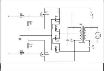
[3] Datasheet of Power MOSFET IRF 840, VISHAY- Document
# 91070, S11-0506-REV.C, 21-Mar-2011
[4] P K Sadhu, G Srkar and A Rakshit, “A microcontroller-
based variable voltage variable frequency sinusoidal power source with a novel PWM generation strategy”, ELSEVIER, Measurement (45) 2012, pp 59 – 67
[5] PIC Microcontroller and Embedded Systems (by Muham- mad Ali Mazidi, Rolin.D Mckinlay, Danny Causey)
[6] PIC Microcontrollers (by Milan Verle) [7] Power Electronics (by H M Rashid)
Figure 6
In this research, an improved novel design of voltage stabi- lizer with low cost, micro-controller and more precised and accurate type is discussed. This design is highly efficient and stable in the following manner:
• Direct AC-AC conversion without rectifying to DC, this im- proves efficiency, reliability and reduces components
• Generation of pulse width modulation (PWM) at power stage to increase the efficiency
• Use of feedback system using digital signal processing
• To minimize the output distortion up to 7%
• Longevity as no wear tear is involved
This design is for just 5 amperes of current and 220 volt AC. Further, some more power switching devices like IGBT or oth- er semi-conductor devices with high switching speed and of higher current ratings could be used for heavy load and in- crease the efficiency. Moreover this design could be easily ad- vanced for heavy industrial loads and three phase systems as well.
Guidaince of Asst. Prof A N Aslam and Lecturer H T Mustafa is highly appreciated for this research work. This project was granted financially by the Ministry of IT of Pakistan.
[1] S Venkatesh and K Muthiah, “Power Fluctuations-usage of servo voltage stabilizers in industry” Journal of Applied Engineering Research, Dindigul, volume2, no1, 2011, pp
283 – 289
[2] P K Banerjee, M A Choudhury and G T Rasul, “AC Voltage
IJSER © 2014 http://www.ijser.org