International Journal of Scientific & Engineering Research, Volume 6, Issue 5, May-2015 273
ISSN 2229-5518
Agility Achievement and Load Handling System in Fat-Tree Data Center Network
Amol Lonare, Ms. Veena Gulhane
Abstract— A multi-rooted hierarchical tree topology is most widely used in many data center networks. It provides good utilization of resources as well as better performance, still fat tree Data Center Network has two limitations i.e traffic load balance and agility. This is because Data Center Networks (DCN) increasingly carries larger and longer traffic flows. As a result of this it is unable to support different traffic types efficiently and has no capacity to access all services by all servers. A work has done previously on load balancing, yet agility has not been solved. In this paper the Agility Handling Method (weighted least connection technique) has been implemented to achieve Agility in Data Center network. This technique improves load handling capacity and also increases the level of performance even in a more number of nodes in the network.
Index Terms— Fat-tree, Data Center Network, Agility, Network Utilization, Load balance, Services.
—————————— ——————————
1 INTRODUCTION
he Data Center Network is a collection of servers that provides various services to the client’s requests. The modern Data Center Network is a hierarchical network provides 1+1 redundancy. The equipment higher in the hier- archy handles more traffic, they are more expensive, take more efforts to make at availability, it is known as the scale up design. Many of today’s data center network uses fat tree to- pology to get the identical bandwidth in the network at any
bisection.
1.1 Background
A Fat-Tree based Data Center Network comprises the racks of servers and the servers in each rack are connected with a Top of Rack (ToR) switch. Here each ToR switch is connected to some aggregation switches, which again connect to top tier in-between switches. In modern data center network servers connect via 1 Gbps UTP to Top of Rack switches. Other links are mix of 1G, 10G; fiber, copper. Data centers (DCs) can be of three types private, public, or virtually private. Private DCs are dedicated to one enterprise, and may support multi- tenancy within the enterprise. They are interconnected over an enterprise-dedicated private network or virtual private net- work. Services within the private DC could remain private to the enterprise and could be partially connected to Internet access via secure gateways. Public DCs are connected via the Internet and are often targeted for Internet-based services, including multi-tenant services as well as commercial public services. Virtual private DCs are built on a common DC infra- structure often provided by a DC provider. Modern data cen- ters might Contain tens of thousands of hosts for supporting the needs of cloud computing, multimedia contents, and big data analysis.
Many topologies and architectures are proposed to address the various purposes and requirements such as cost reduction, energy reduction, and support for scalability. Moreover, the construction of a data center incurs significant costs. Further, there are many technologies that can affect the structure of data centers [1]. Therefore, Todays data center network uses a multi rooted fat tree topology to build a data center network. All currently deployed most of the Data Center Networks
(DCNs) trust on layer-3 Equal Cost Multipath routing to uni- formly distribute traffic and utilize the gathered capacity pro- vided by the multi-tier network. The longer and larger flow of bandwidth characterizing different phases break the nice traf- fic spreading provided by the ECMP hash function for many low-bandwidth flows. Under such hash-based traffic spread- ing, the probability of over-subscription follows the balls-and- bins max-load distribution [1]. The contending flows result in low effective bandwidth.
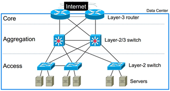
Figure 1. Example of fat tree topology
In addition to compute and storage infrastructure, services
are also offered from public and virtual private data centers
connected across the Internet or virtual private networks. In all cases, time varying demands in terms of computing, stor- age, connectivity, and bandwidth coupled with the need to optimize for power consumption, cost, and resiliency requires
service provisioning agility. Existing architectures of the data center network does not provide sufficient capability between the servers to which they are interconnected. The Data-center networks perform less to keep an excess of traffic to one ser- vice from affecting others service. And the routing scheme allocates servers topologically at significant IP address and distributes servers among virtual local-area networks, striking a huge configuration burden when the traffic must be reas- signed among services. Therefore agility should be provided in data center network.
Agility [2] property represents the ability of Server to re-
IJSER © 2015 http://www.ijser.org
International Journal of Scientific & Engineering Research, Volume 6, Issue 5, May-2015 274
ISSN 2229-5518
spond rapidly to the changing environment. Virtualization will not fully deliver its promise of agility as long as networks are statically provisioned and managed. Agility handling method is designed to address the agility in a fat tree data cen- ter network. This is an ability to assign any service to any server and on the request of client any server has to provide any service without affecting the each other’s service in data center network.it also take care of the traffic load on network and balance the load while providing the services.
1.2 Related Work
Many researchers has worked on fat tree based data center network to address various limitations and handling the traffic load in various traffic types.
For unicast scheduling, most existing data centers adopt ECMP (Equal Cost Multi-Path) [3] scheduling, which splits traf- fic load across multiple paths by forwarding each packet via the path determined by a hash function of selected fields in the packet’s header. ECMP routing is deterministic and fixed, be- cause it is based on the constant hash functions of the flow iden- tifier. The achieved bandwidth from these techniques is nearby to the networks cross bisectional bandwidth when the flow granularity is small, it means that the routing algorithm extents many flows that are either short or of low-bandwidth.
ECMP consider the parameters throughput, traffic pattern and flow capacity. With ECMP traffic can be distributed be- tween the rests of the equal paths in a sub second and without severe loss of traffic. It is used mainly on the flow level traffic pattern.
A limitation of ECMP is that the large and long-lived (“ele- phant”) flows navigating a router is mapped to the same output port. This type of “collisions” can cause load imbalances into a multiple paths and cause network bottlenecks, which results in large bandwidth losses, also the load balancing is criticized due to impact of rapidly changing latency.
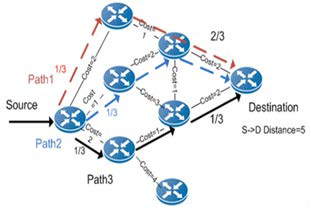
Figure 2. ECMP Load Balance
For giving unpredictability and divergence of a traffic pat- tern in a data center network routing protocol should be de- signed to balance the data center traffic by fully exploiting the path diversity in fat-tree. VLB (Valiant Load Balancing) [4] is a simple-yet-efficient load balancing technique that performs des-
tination independent random traffic spreading across interme- diate switches. In a data center with TCP/IP communications, it is, however, generally believed that packet based VLB is not suitable. The receiver generates duplicate ACKs (acknowl- edgements) for out-of-order packet arrivals. As a result, the data center network utilization will be significantly lowered. To avoid the packet out-of-order problem, existing fat-tree based data center networks adopt flow-based VLB, where the routing objective is to balance the number of TCP flows traversed through each switch. Since packets of the same flow always follow the same path, there is no packet out of-order problem. But if the traffic in a data center contains elephant flows (i.e. large and long-live TCP flows) [5], flow based VLB schemes can cause congestion on hotspot links. To address this issue, dy- namic flow scheduling can be used to identify and reassign ele- phant flows. In a central scheduler with knowledge of all active flows is used for flow reassignment. More recently, multipath TCP (MPTCP) [5], [6] is adopted for improving the load balanc- ing performance in data centers.
various techniques for balancing the traffic load in Data Center
Network is used on the basis of two parameters bandwidth and
traffic flow where each technique has some limitations.
1.3 Contribution
In agility handling work we considered the three of above limitations to overcome, first limitation is that system is not suitable for larger and non-uniform traffic, second is increase the packet latency and third is not work with the changing envi- ronment. In agility handling method three parameters has been considered bandwidth, traffic pattern and network link capaci- ty. In a data center network many work has done to address various limitations but no work has done to achieve the agility in Fat-Tree Data Center Network. This is the motivation for de- signing this agility handling system.
The paper is ordered as follows. Section II introduces a research design of the system. In Section III, presents agility handling work with architecture of system and load balance technique. Section IV contains implementation guidelines for weighted least connection method. Section V contains Impact of agility handling system. Section VI contains outcomes of the system and Section VII describes a discussion and conclusion
2 RESEARCH DESIGN
2.1 Objectives
In research of achieving agility and improving the traffic load balance, the new approach has been implemented to fulfill following objectives
The objectives of agility handling system are:
1. To achieve Agility (i.e any server has to provide any service)
in fat tree Data Center Network.
2. To provide performance isolation (i.e services should not
affect each other).
3. To improve the Traffic load balance.
2.2 Architecture
Architectural model shown in Figure 3 describes the work- ing of agility handling system. Data center is a cluster of large
IJSER © 2015 http://www.ijser.org
International Journal of Scientific & Engineering Research, Volume 6, Issue 5, May-2015 275
ISSN 2229-5518
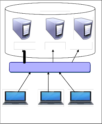
number of computers operated and managed by a single au- thority. In this system first we are going to create a data center network with minimum four servers. This data center will be created by using a hierarchical topology. The system is divid- ed into three parts where first part will be the data center con- taining some nodes and each node having services in it. Se- cond part will be the centralized server called balancer; it will handle the load and address the agility in data center network. Third part will be the client which will access services from defined servers. Here client will sent the request to server to get the service and server will send the reply to clients request, this is the normal flow of network. When number of clients will send the request at the same time to the same server then load balancer will check out the traffic on server side. If there will be more requests to the same server immediately it will transfer to the nearby server not having more traffic to reply with the same service.
DCN
It can be seen that at each layer of the tree, the number of links connecting to the next layer is the same, giving a constant bandwidth between layers. The core layer has switches, and the aggregation and access layers have switches each. The switches at aggregation and access layers are grouped into pods, and each pod supports servers. The fat-tree as a whole supports servers using port switches. For inter-pod communi- cations, e.g. between servers say A and D (if A,B,C,D are at bottom layer), there are 6-hop paths. For intra-pod communi- cations, there are 4-hop paths if the two servers are not con- nected to the same access switch (e.g. servers A and C); other- wise, there is only one 2-hop path (e.g. servers A and B). Rout- ing a packet in fat-tree consists of two phases: up routing and down routing. In the up routing phase, a least common ances- tor (i.e. a turning switch) of the source and the destination is determined. If there are more than one candidates, e.g. there are 4 candidates from source A to destination D, the selection is based on the specific routing algorithm adopted. If a turning switch is chosen, the path from the source to it, as well as the path from it to the destination, becomes unique. To exploit the path diversity, load balancing is performed during upstream routing, which can be either packet-based or flow-based. Flow-based VLB [8] aims at spreading TCP flows evenly among upstream aggregation and core switches. Although multiple paths exist, packets of the same flow can only follow the same selected path (i.e. the path selected for the first pack- et of the flow). Due to the coarse load balancing granularity, it
Server-1
Server-2 Server-3
is difficult for flow-based VLB to fully utilize the fat-tree’s full bisection bandwidth. Therefore least weight connection rout- ing is chosen to fully utilize the bandwidth.
Agility Handler & Load Balancer
Client-1 Client-2
Fig. 3 Architecture of agility handling system
2.3 Routing in Fat-tree
Client-3
2.4 Agility and load balance
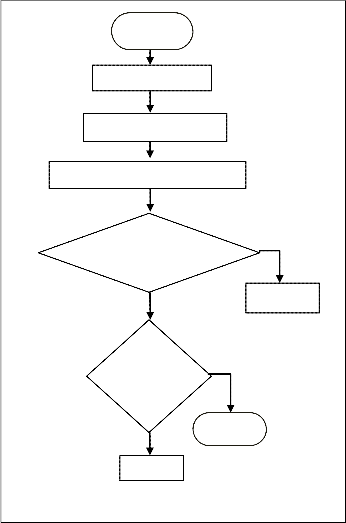
Figure 4 shows the flow of load balancing and agility method. Load balancing [9] allows distributing client requests through multiple servers. Load balancers also improve the fault toler- ance of server and end-user response time. This Load balanc- ing technique distributes client requests into multiple servers to optimize resource utilization. In the case where the limited numbers of servers are used to provide service to a large number of clients, hare servers become overloaded and reduce server performance. This Load balancing is used to prevent the bottlenecks by sending the client requests to the servers which is best suited to handle them.
To address the agility and balance the load in agility handling system we are going to use load balancing method named weighted least-connection [10]. The weighted least-connection scheduling is the higher than the least-connection scheduling algorithm and here we can assign a performance weight to each real server. The servers having a higher weight value will
Without loss of generality, we consider a three-layer fat-tree
[7] constructed using port commodity Ethernet switches and
bidirectional links, as shown in Fig. 1.
accept a larger percentage of active networks at any one time.
IJSER © 2015 http://www.ijser.org
International Journal of Scientific & Engineering Research, Volume 6, Issue 5, May-2015 276
ISSN 2229-5518
Start
No. of Server
Assign Weight to all
Check the Load of a server
Server1 < Serv- er2
No
Check
for Oth- er Server
Stop
Repeat
Fig. 4 Flow of Load handling method.
Yes
Server 1
• Server-2 is having 15 active transactions.
• Server-3 is not having any of the active transactions.
The load balancer now selects the service by considering the value (N)
Where N the number of active transactions
The requests are transferred as follows:
• Server-3 accepts the first request because here no any active transactions are handled by the service.
Note: - The service without any active transaction is selected first.
• Server-1 accepts the second and third requests because here the service has the least number of active connections and so as weight.
• Server-2 receives the fourth request and so on.
When the Server-1 and the Server-3 have equal number of ac- tive connections, the balancer performs load balancing using a round robin concept. Therefore, Server-3 accepts the fifth re- quest, Server-1 accepts the sixth request, Server-3 accepts the seventh request, and Server-1 accepts the eighth request and so forth. Hence the work load will be reduced than the virtual data center [12] system provides.
3 IMPLIMENTATION
In this section implementation of the agility handling system has discussed with working of algorithm, pseudo code, exper- imentation setup, execution and analysis.
3.1 Working of algorithm
Suppose a given server set is S = {S0, S1, ….. Sn-1}, Wi (i=1,..,n) is the weight of each server i..
The default server weight is one, and Administrator or Load Balancer can assign any weight to real server. And in a weighted least connection scheduling algorithm, the new net- work connections are assigned to the server that has the very least ratio of current dynamic connection number for its weight.
In a load balancing concept, the load balancers are logically placed between the client and the server. Load balancing is used to manage the traffic flow between the servers in a server networks. When a load balancer is designed for using the weighted least connection method and selects the service with the minimum number of active connections and minimum assigned weight for ensuring that the load of the current active requests is balanced on the services. This scheme is the useful load balancing scheme as it provides the best performance in a changing environment. It is also energy efficient than the pre- vious energy efficient [11] method.
The following example shows that how a weighted least- connection selects a service for load balancing in a data center network.
Consider the following three services:
• Server-1 is having 3 active transactions.
Ci (i=1,..,n) is the current connections. ALL_CONNECTIONS is the sum of Ci (i=1,..,n),
the next network connection here will be send to the server j, in which
(Cj/ALL_CONNECTIONS)/Wj = min { (Ci/ALL_CONNECTIONS)/Wi } ( i=1,..,n )
Since, here the ALL_CONNECTIONS is constant. Hence, in this case it is not needed to divide Ci by ALL_CONNECTIONS and it can be enhanced as
Cj/Wj = min { Ci/Wi } (i=1,..,n)
The scheduling gives an assurance that the server will not
be scheduled when its weight is zero.
Below given the pseudo code for weighted least connection
scheduling algorithm.
Begin
Step 1: for each j = 0 to N
Step 2: check if W(Sj) > 0
Step 3: for each i = j+1 to N
Step 4: check if (C(Sj)*W(Si) > C(Si)*W(Sj))
Then
j = i
( End of if )
Step 5: return Sj;
IJSER © 2015 http://www.ijser.org
International Journal of Scientific & Engineering Research, Volume 6, Issue 5, May-2015 277
ISSN 2229-5518
( End of Loop 2) Step 6: return NULL;
( end of loop 1) End
3.2 Experimental Setup
Agility handling method to achieve agility and balance the traffic load is implemented in real time using a hardware module. The setup of the project consist of four servers each having four services i.e uploading ,downloading, chatting and mailing. Each server is having its own database and many clients can registered with each server. Here each server is connected with other server so that it can easily divert the re- quest of client to another server and each server can work as a central server, this is to reduce the number of resources and thereby reduce the cost of network.
3.3 Execution of method
For experimental execution the agility handling method is implemented in dot net technology with SQL server as a data- base. While execution many clients will be connected with each server separately. Only the registered clients can access the services. Consider the 4 clients are connected with the server 1, 3 clients are connected with the server 2, 5 clients are connected with the server 3 and 5 clients are connected with the server 4. The central server will calculate the load on each server first based on the number of active clients on respective server. When the request is made to the server for any service then central server will check the load on each server because it has a record of load on each server and instantly the request will divert to the server having minimum load. Once that server receives the request it will be fulfilled and client will get the service without waiting for longer time. Here the user can check that to which server he is connected and from which server the request have been fulfilled.
During execution three parameters has been consid- ered i.e bandwidth of data flow, packet loss and transmission delay. Agility handling system gets the value of these parame- ters from each server and calculates the average delay and losses. These parameters are then compared with the previous method i.e ECMP Routing and show the comparison in form of graph.
3.4 Result and analysis
For analysis above parameters of agility handling system are compared with the existing ECMP method. Following table shows the comparative analysis of result.
TABLE 1
COMPARATIVE ANALYSIS OF METHODS
Parameters | Methods | Performance improvement (in %) |
Parameters | ECMP | Agility handling Method | Performance improvement (in %) |
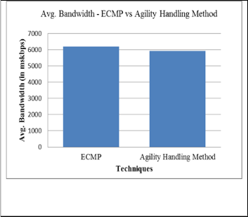
Avg. Bandwidth ( in kbps) | 6189 | 5933 | 4.13 |
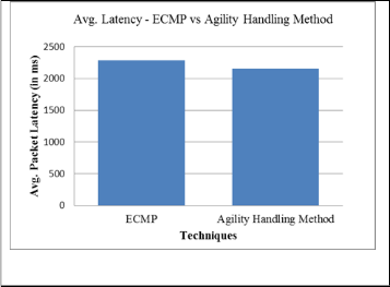
Avg. Packet la- tency (in ms) | 2289 | 2158 | 5.72 |
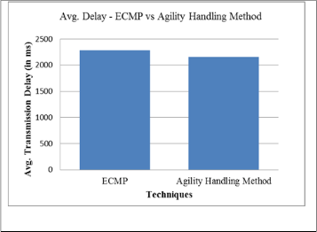
Avg. Transmis- sion Delay (in ms) | 2289 | 2158 | 5.72 |
The graphical representation of the analysis of agility handling method is shown in following graphs. The graph shows that agility handling method is better than the existing ECMP technique.
Fig. 5 analysis of average bandwidth
The average bandwidth of DCN using agility handling meth- od has been improved by 4.13 percent than old method.
IJSER © 2015 http://www.ijser.org
International Journal of Scientific & Engineering Research, Volume 6, Issue 5, May-2015 278
ISSN 2229-5518
Fig. 6 Analysis of average packet latency
The average latency of DCN using agility handling method has been improved by 5.72 percent than old method.
Fig. 7 Analysis of average packet latency
The average delay of DCN using agility handling method has been improved by 5.72 percent than old method.
4 IMPACT OF AGILITY HANDLING SYSTEM
The agility handling system has created an agile data center network which provides any service by any server without affecting the each other’s services. Through this system clients get the fast response of their requests. The network is flexible and works in a changing environment. This agility handling system provides an improved performance of data access in organization also various big data applications are handled by Data Center Network. It gives the customer the impression of having infinite resources that can raise and contract whenever they want, and it gives us the ability to distribute that at a very low cost.
5 CONCLUSION
In this project a new technique has been implemented to achieve agility in a fat-tree based data center network. To achieve agility, the weighted least connection technique has been adopted, which also balances the load in a fat-tree data center network. So it is concluded that this system achieved agility in a Fat-tree Data Center Network and make DCN able to provide any service by any server as per client’s request. The system is also checked for the performance isolation and it is found that during the fulfillment of client’s request no ser- vice has been affected by any other service, hence it provides performance isolation. While achieving agility in DCN, traffic load has distributed among servers and load handling capaci- ty has improved. In Agility Handling System, bandwidth is improved by 4.13 %, latency is improved by 5.72% and trans- mission delay is improved by 5.72%, thus the overall perfor- mance of system is improved by 5% as compared to ECMP system. Hence the Agility Handling System will be helpful to reduce the data Centre cost and resource utilization.
ACKNOWLEDGMENT
The research work presented in this paper has done by Amol Lonare, a student of final semester computer science and en- gineering. The agility handling research work has been com- pleted under the guidance of Prof. V.A. Gulhane. The agility handling method has been implemented and tested by using the hardware modules.
REFERENCES
[1] Zhiyang Guo, Jun Duan and Yuanyuan Yang, “On-line Multicast Scheduling with bounded congestion in fat-tree data center networks,” journal on selected areas in communications, vol. 32, no.
1, 0733-8716/14 IEEE 2014
[2] Eitan Zahavi, Isaac Keslassy, and Avinoam Kolodny, “Distributed adaptive routing convergence to non-blocking dcn routing assignments,” journal on selected areas in communications, vol. 32, no. 1, 0733-8716/14, IEEE 2014.
[3] yoonseon han, sin-seok seoy, chankyou hwang, “flow-level traffic matrix generation for various data center networks ,“ 978-1-4799-
0913-1/14,IEEE 2014.
[4] pi-chung wang , “scalable packet classification for datacenter networks ,“ journal on selected areas in communications, vol. 32, no.
1, 0733-8716/14, IEEE 2014.
[5] andres ferragut and fernando paganini, “network resource allocation for users with multiple connections: fairness and stability ,“ transactions on networking, vol. 22, no. 2, 10.1109/tnet.2013.2251896, IEEE 2014.
[6] jijun cao, kefei wang, xin wang, “back-track routing for fat-tree based data center networks, “ international conference on cloud computing technology, 978-0-7695-5095-4/13, IEEE 3013.
[7] zhiyang guo, jun duan and yuanyuan yang, “Oversubscription
Bounded Multicast Scheduling in fat-tree data center networks ,“
27th international symposium on parallel & distributed processing,
10.1109/ipdps.30, IEEE 2013.
IJSER © 2015 http://www.ijser.org
International Journal of Scientific & Engineering Research, Volume 6, Issue 5, May-2015 279
ISSN 2229-5518
[8] ali munir, ihsan a. qazi, zartash a. uzmi, aisha mushtaq, “minimizing flow completion times in data centers ,“ proceedings ieee infocom
978-1-4673-5946-7/13- IEEE 2013.
[9] fung po tso, dimitrios p. pezaros, “improving data center network utilization using near-optimal traffic engineering,” ieee transactions on parallel and distributed systems, vol. 24, no. 6, 1045-9219/13, june
2013.
[10] yu cao, mingwei xu, “dual-nat: dynamic multipath flow scheduling for data center networks, “ 978-1-4799-1270-4/13 IEEE
2013.
[11] hao jin, tosmate cheocherngngarn, dmita levy , “joint host-network optimization for energy-efficient data center networking,“ 27th international symposium on parallel & distributed processing, 1530-
2075/13 IEEE 2013.
[12] yiduo mei, ling liu, xing pu, sankaran sivathanu, and xiaoshe dong , “performance analysis of network i/o workloads in virtualized data centers,“ transactions on services computing, vol. 6, no. 1, 1939-1374
IEEE 2013.
IJSER © 2015 http://www.ijser.org