International Journal of Scientific & Engineering Research, Volume 5, Issue 1, January-2014
ISSN 2229-5518 1899
ANALYSIS OF SPREAD SPECTRUM IN MATLAB
Vishal Sharma, Richa Sharma
Index Terms— Error probability, noise, power spectral density, error rate performance, Chipping code, AWGN.
![]()
-------------------------------- ------------------------------------
I. Introduction
Initially the intended applications for spread spectrum is on military purposes but through the years there have several functions including Global Positioning System (GPS) which are mainly used to transmit at low power without jamming interference to other users or multi-path propagation.
Spread spectrum transmitters use a periodical pseudo-random
sequence to modulate the baseband signal before transmission. A receiver, which does not know the sequence, cannot demodulate the signal. The spread spectrum techniques are useful for secure transmitter, because the receiver has to know the sequence used by the transmitter to recover the transmitter data.
Our purpose is to automatically determine the spreading sequence, whereas the receiver has no knowledge of the transmitter’s code. Matlab simulations will examine the code
III. Probability of Error
In an AWGN channel, the probability of error for a DS spread spectrum system employing binary PSK is identical to the probability of error for conventional binary PSK
Pb=Q(√(2Lb/Ne)) (1)
On the other hand, if the interference is the sin signal given by below equation with power Pj, the probability of error is
Pb = Q (√ (2Lb/Pj/ w)) = Q (√ (2Lb/Je)) (2)
Thus, the interference power is reduced by the factor of the spread spectrum signal bandwidth W. in this case; we have ignored the AWGN, which is assumed to be negligible.
IJSER
estimation performance of the proposed algorithm.
II. Direct Sequence Spread Spectrum
In telecommunications, direct-sequence spread spectrum (DSSS) is a modulation technique. As with other spread spectrum technologies, the transmitted signal takes up more bandwidth than the information signal that is being modulated. The name 'spread spectrum' comes from the fact that the carrier signals occur over the full bandwidth (spectrum) of a device's transmitting frequency.
Features
1. It phase-modulates a sine wave pseudo randomly with a continuous string of pseudo noise (PN) code symbols called "chips", each of which has a much shorter duration than an information bit. That is, each information bit is modulated by a sequence of much faster chips. Therefore, the chip rate is much higher than the information signal bit rate.
2. It uses a signal structure in which the sequence of chips produced by the transmitter is known a priori by the receiver. The receiver can then use the same PN sequence to counteract the effect of the PN sequence on the received signal in order to reconstruct the information signal.
![]()
Vishal Sharma is currently pursuing Ph.D. degree in Quantum Cryptography and Coding in IIT Jodhpur, Rajasthan, India Ph. +919462101242
Richa Sharma is currently pursuing M.Tech degree
I.e., Ne<< Pj/W. If we account for the AWGN in the channel,
the error probability is expressed as
Pb = Q (√ (2Lb/Ne+Pj/W)) = Q (√ (2Lb/Ne+Je)) (3)
(For simulated output see Fig 1, Fig 2 and Fig 3)
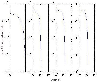
Fig 1: Simulation results of DSSS with different Interferences
IV. Frequency Hopped Spread Spectrum
In frequency hopped spread spectrum the available channel bandwidth W is subdivided into a large number of no overlapping frequency slots. In any signaling interval the transmitted signal occupies one or more of the available frequency slots. The selection of the frequency slot in each signal interval is made pseudo randomly according to the output from a PN generator.
The modulation is either binary or M-ary FSK. For example if binary FSK is employed, the modulator selects one of two
IJSER © 2014 http://www.ijser.org
International Journal of Scientific & Engineering Research, Volume 5, Issue 1, January-2014
ISSN 2229-5518 1900
frequencies, f0 or f1 corresponding to the transmission of a0 or a1. The resulting binary FSK siganl is translated in frequency by an amount that is determined by the output sequence from PN generator which is used to select a frequency fc that is synthesized by the frequency synthesizer. This frequency-translated signal is transmitted over the channel. For example, by taking m bit form the PN generator, we may specify possible carrier frequencies.
(For all figures X axis stands for Signal-to-Noise Ratio in dB, Y axis refers to the error rate)
also, in the propagation of the signal over the channel as the signal is hopped from one frequency to another over a wide bandwidth. Consequently, FSK modulation with non-coherent demodulation is usually employed in FH spread spectrum systems.
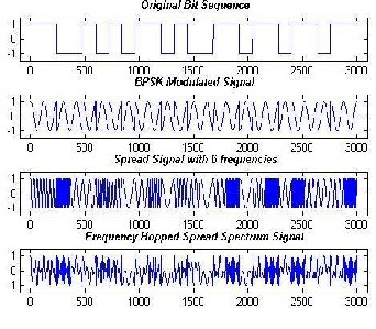
Fig 2: DSISS SignJal
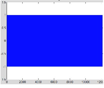
Fig 4: Simulation results of FHSS
SER
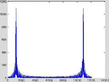
Fig 3: FFT of DSSS Signal
At the receiver, there is an identical PN sequence generator, synchronized with the received signal, which is used to control the output of the frequency synthesizer. Thus the pseudorandom frequency translation introduced at the transmitter is removed at the demodulator by mixing the synthesizer output with the received signal. The resultant signal is then demodulated by means of an FSK demodulator, a signal for maintaining synchronism of the PN sequence generator with the FH received signal is usually extractor form the received signal.
Although binary PSK modulation generally yield better performance than FSK , it is difficult to maintain phase coherence in the synthesis of
the frequencies used in the hopping pattern and,
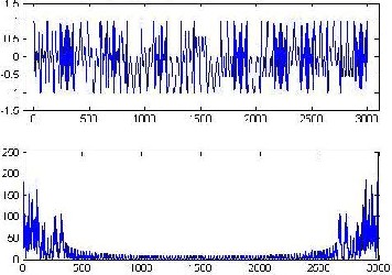
Fig 5: Frequencies Hopped Spread Spectrum Signal and its FFT
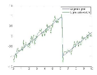
Fig 6: Simulated output Signal with AW GN
IJSER © 2014 http://www.ijser.org
International Journal of Scientific & Engineering Research, Volume 5, Issue 1, January-2014
ISSN 2229-5518 1901
The frequency hopping rate, denoted as Rh, may be selected to be either equal to the symbol rate, lower than the symbol rate, or higher than the symbol rate. If Rh is equal to lower part at the symbol rate, the FH system is called a slow hopping system.If Rh is higher than symbol rate, the FH system is called a fast hopping system. (For simulated output see Fig 4 and Fig 5)
V. Pseudorandom Sequence
Definition of pseudo random sequence: A pseudorandom sequence is a code sequence of 1’s and 0’s whose autocorrelation has properties similar to those of white noise.
It is 'pseudo' because it is deterministic and after N elements it starts to repeat itself, unlike real random sequences, such as sequences generated by radioactive decay or by white noise. The PRBS is more general than the n-sequence, which is a special pseudo-random binary sequence of n bits generated as the output of a linear shift register. An n-sequence always has a 1/2 duty cycle and its number of elements
N = 2 − 1k. PRBS's are used in telecommunication, encryption, simulation, and correlation technique and time- of-flight spectroscopy.
Pseudo-random number generators: Pseudo-random number generators (PRNGs) are algorithms that can automatically create long runs (for example, millions of numbers long) with good random properties but eventually the sequence repeats exactly (or
applications. Most computer programming languages include functions or library routines that purport to be random number generators. They are often designed to provide a random byte or word, or a floating point number uniformly distributed between 0 and 1.
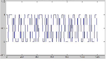
Fig 8: Pseudorandom Bit Sequence.
Correlation properties of PN sequence: The autocorrelation function is very important for periodic PN sequence, which is usually defined in terms of bipolar sequence {Cn} as
the memory usage grows without bound). One of the most
common PRNG is the linear congruential generator, which uses![]()
Rc(m) = σ …… •
_• _
_ (4)
the recurrence to generate numbers.The maximum number of numbers the formula can produce is the modulus, m. To avoid
Where L is period of the sequence. Since the sequence
{Cn} is periodic with period L, the autocorrelation sequence
IJSER
certain non-random properties of a single linear congruential
generator, several such random number generators with slightly different values of the multiplier coefficient a are typically used in parallel, with a "master" random number generator that selects from among the several different generators. A simple pen-and- paper method for generating random numbers is the so-called middle square method suggested by John Von Neumann. While simple to implement, its output is of poor quality.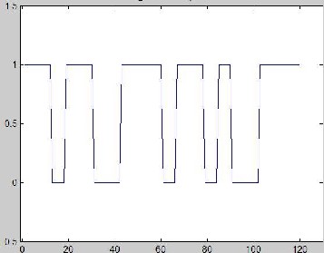
Fig 7: Original Bit Sequence.
A PRNG can be started from an arbitrary starting state, using a seed state. It will always produce the same sequence thereafter when initialized with that state. The maximum length of the sequence before it begins to repeat is determined by the size of the state, measured in bits. However, since the length of t he maximum period potentially doubles with each bit of 'state' added, it is easy to build PRNGs with periods long enough for many practical
{Rc(m)} is also periodic with period L.
In some application the cross correlation properties of PN sequence are as important as autocorrelation properties. For example, Pseudo-random sequence with good correlation property and large linear span is widely used in code division multiple access (CDMA) communication systems and cryptology for reliable and secure information transmission. In this paper, sequences with long period, large complexity, balance statistics, and low cross-correlation property are constructed from the addition of m- sequences with pair wise- prime linear spans (AMPLS). Using m-sequences as building blocks, the proposed method proved to be an efficient and flexible approach to construct long period pseudo-random sequences with desirable properties from short period sequences. (Fig 7 and Fig 8 shows Original bit sequence and Pseudorandom Bit Sequence respectively)
VI. DS vs. FH
Based on simulated output figures we can make following comparisons
1. FH is more secure than DS.
2. DS has fine resolution, rapid switching and rapid settling a practical reality at reasonable cost.
3. Interference rejection:
(i) DS systems accept levels of interference a little bit higher that those accepted by FS systems;
(ii) However if the interference is higher than the limit the DS stop to work but the FS try to use unaffected frequency and continue to work.
(iii)For signals lower than the jamming margin, the DSSS system throughput is unity, which means that every packet sent can be accurately received.
IJSER © 2014 http://www.ijser.org
International Journal of Scientific & Engineering Research, Volume 5, Issue 1, January-2014
ISSN 2229-5518 1902
(iv)DS systems are affected by high levels of interference created by other DS systems using the same band but different codes.
4. Throughput
(i) DS systems transmit continuously (PSK). FS spend some time to re-synchronize and for hopping (FSK);
(ii) DS systems may have a better throughput for same data rate over the air.
5. If the interferer is within the spreading band, then the DSSS system can tolerate and completely reject it while the FHSS system can be completely jammed on that channel. For a large out-of-band interferer, the opposite is true. The DSSS process is sensitive to such interferers, where the FHSS system is not.
6. FH has to be placed far away before there interference with the other group is minimized. DS, on the other hand can be placed much closer to other DS on the same channel due to the interference resistant nature of the DS waveform.
7. Power density: DS achieve very low power spectral density, therefore minimizes interference. FH has higher power spectral density which is not as good as DS since more transmit power is needed.
8. Hardware requirement: FH can be handled with a simple analog limiter receiver while DS requires complex base band processing. DS requires higher logic speeds and more complex processing.
VII. Conclusion
Digital Communication has vital role in different areas. Spread Spectrum becomes more and more popular. DS and FH are the two major method of Spread Spectrum. They have different strongpoint and are equally important. M-sequence and Gold- sequence have almost the same performance with single information transmission. However, the multi-user situation is demanded now a days. AWGN is usually used as the noise channel during simulation. But for wireless communication, Rayleigh Fading Flat Channel should be used instead to represent the communication channel. To block multiuser interference selected and error free binary sequences are required.
VIII. References
[1]. John G. Proakis and Masoud Salehi, “Contemporary
Communication Systems Using MATLAB”
[2]. Roger L. Peterson, Rodger E. Ziemer and David E.
Borth, “Introduction to Spread Spectrum Communications”
[3]. Adrian Biran and Moshe Breiner, “MATLAB”
[4]. George R. Cooper, Clare D. McGillem, “Modern communications and spread spectrum”
[5]. Theodore S. Pappaport, “Wireless Communications principles and practice”
[6]. M. Elkashlan and C. Leung, “Performance of
Frequency-Hopping Multicarrier CDMA in Rayleigh Fading”
[7]. Carl Andren, “A Comparison of Frequency Hopping and
Direct Sequence Spread Spectrum Modulation for IEEE
802.11 Applications at 2.4 GHz”
IJSER © 2014 http://www.ijser.org