International Journal of Scientific & Engineering Research, Volume 3, Issue 6, June-2012 1
ISSN 2229-5518
An Overview of Active Front Steering System
Er. AMITESH KUMAR, Dr.Dinesh.N.Kamble
ABSTRACT - The kinematic models of planetary gear set and steering gear are established, based on the analysis of the transmission mechanism of angle superposition with Active Front Steering system (AFS). A controller of variable steering ratio for Active Front Steering system is designed, and virtual road tests are made in Car Maker driver- vehicle-road simulation environment. The results of simulation tests validate the controller performance and the advantage of variable steering ratio function, also show that the driving comfort is improved at low speed especially, due to the Active Front Steering system alters the steering ratio according to the driving situation
Keywords – Planetary gear mechanism, AFS Actuator, electronic Motor with electromagnetic locking system, Simulation and result analysis, Safety interface, Slalom test, kinematic stabilization function.
—————————— ——————————
1. INTRODUCTION
1.1 Concept
The steering system acts a significant role of making car convenient to handle and enhance the vehicle stability. In the past one hundred years, the development of steering system has experienced many
stages, and the Steer-by-Wire system (SBW) is the newest technology of steering system for passenger cars. But the Steer-by-Wire system has not yet accepted by public consumers and permitted by state regulations, in consideration of the reliability and safety of the system.
Active Front Steering (AFS) is a newly technology for
passenger cars developed by BMW, that implements an
electronically controlled superposition of an angle to
the hand steering wheel angle that is prescribed by the
driver. However, the permanent mechanical connection between steering wheel and road wheels remains. AFS
could adjust the vehicle performance by means of intervening the road wheel angle in condition of the driver have top priority, which avoid the people's concerns about the Steer-by-Wire system.
A lot of studies about the active steering system are carried out all over the world. But most of the studies focus on the stability of vehicle, which apply AFS, as in. As a basic function of active steering system, the driver will experience the variable steering gear ratio function at first, and perceive the improvement of steering portability. AFS enables continuous and situation- dependent variation of the steering ratio according to the vehicle’s motion state, therefore AFS improve the maneuverability of the vehicle at low speed and the stability at high speed. The performances of stability improvement with active steering system depend upon the quality of variation of the steering ratio to a certain extent. Thence, it is significant to investigate the variable steering gear ratio function.

 Er. Amitesh Kumar (Mechanical Engineer) Masters of Engineering in Automotive Engineering from Sinhgad Academy of Engineering, Pune, India.
E-mail: amitesh.parasar@gmail.com
 Dr. Dinesh N Kamble (Professor) Mechanical Engineering Dept. at
Sinhgad Academy of Engineering, Pune, India.
1.2 How's it Works
IJSER © 2012
http://www.ijser.org
International Journal of Scientific & Engineering Research, Volume 3, Issue 6, June-2012 2
ISSN 2229-5518

Figure 1: (a) Schematic view of AFS system; (b) 3D-model of planetary gear set and electric motor
The steering gear’s pinion angle  is dependent up on the steering wheel angle
  and motor angle
  and there is a nonlinear relationship between the average front road wheel steering angle
  and the pinion angle. Hence, the front wheel angle
  which relies on the pinion angle
  would be changed with variation of the motor angle
  when given a certain hand steering wheel angle
  such is the function of variable steering gear ratio. The above relationships are showed as follow:


V (t) S (t)  M (t) (1) f (t) F ( V (t)) (2)
  1 /
1 /  S (t) (3)
Where  denotes the steering gear’s pinion angle,
  the hand steering wheel angle,
  the motor angle,
  average front road wheel angle,
  the factor of conversion from hand steering wheel angle to the steering gear’s pinion angle,
  the factor of conversion from motor angle to the steering gear’s pinion angle, F(•) denotes the nonlinear relationship between the average front road wheel steering angle
  and the pinion angle
  is defined as the steer ratio of active steering system,

1.3 Layout

Beyond that, AFS mainly includes two core components: a set of planetary gears which are used to change the drive ratio by applying an additional angle to steering box; Electronic servo steering system, which provides assist steering power for driver. Driver's steering input can be divided into torque input and angular input, both will be passed to the torsion bar. The input angle is added to the dual planetary gear mechanism. Figure 2 shows the steering angle superposition principle. The significant difference with conventional steering system is that AFS can not only adjust steering torque, but also regulate the steering angle and make it match the current vehicle speed perfectly.
Figure 2: Structure of AFS
IJSER © 2012
http://www.ijser.org
International Journal of Scientific & Engineering Research, Volume 3, Issue 6, June-2012 3
ISSN 2229-5518
2. MODELLING
2.1 Model
The functionality of AFS is defined by the so-called hardware oriented (low level) and the user oriented (high- level) functions. These functions can also be classified into application and safety functions. Compared with traditional mechanical steering system, active steering system is comprised of a double planetary gear and an electric actuator motor additionally, besides the primary mechanical steering system. Because all the links from the steering wheel to road wheel are mechanical, it is indubitable that AFS is reliable and safe. AFS could ensure that the vehicle is under driver's control all the time, and make driver have a clear road feel. The planetary gear of AFS have two degrees of freedom (DOF), the output of the planetary gear connects with the steering gear’s pinion, and one input connects with the steering wheel, and the other input connects with an electric actuator motor.
2.2 Components
The electric motor (see Figure 3) generates the required electrical torque for the desired motion of the AFS actuator. This synchronous motor has a wound stator, a permanent magnet rotor assembly and a sensor to determine the rotor position. The motor torque is controlled by a field oriented control. This control strategy transforms the stator currents into the torque and rotor-flux-producing components. These current components can be controlled separately and do not depend on the rotor angle. The motor angle sensor is based on a magneto-resistive principle and includes a signal amplification and a temperature compensation. This sensor signal is used for control and monitoring purposes. In analogy to the motor angle sensor, the pinion angle sensor is also based on a magneto-resistive principle and includes a signal amplification and a temperature compensation. This sensor also includes a CAN interface which enables other control systems like ESP to directly use the raw signal. The pinion angle is used as an input to the steering assistance functions and for monitoring purposes. The metal stud of the electromagnetic locking unit (ELU) is pressed towards the worm-locking gear by a spring. This mechanism is unlocked by a specific current supplied by the ECU. The ELU locks the worm (Figure3) if the system is shut down and in case of a safety relevant malfunction. In this case the driver is able to further steer with a constant steering ratio (i.e. the mechanical ratio).The electronic control unit developed for the AFS system establishes the connection between the electrical system of the vehicle, the vehicle CAN – bus, the AFS sensors and the electric motor.
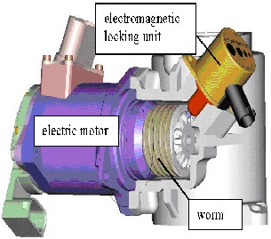
Figure 3: Electric Motor and Electromagnetic Locking Unit
The core components of the ECU are two microprocessors. They perform the computations required for control, monitoring and safety purposes. Via the integrated power output stages, the electric motor, the ELU, the ECO–pump and the Servotronic subsystem are controlled. The microprocessors also perform redundant computations and monitoring. The basis of the AFS system is the well-tried and reliable rack and pinion power steering system. The core subsystem of AFS is the mechatronic actuator which is placed between the steering valve and the steering gear (see Figure 4). The actuator includes the planetary gear set with two mechanical inputs and a single mechanical output. The servo-valve connects the input shaft of the planetary gear with the steering column and the steering wheel. The second input shaft is driven by the electric motor and is connected to the planetary gear by the worm and worm wheel. The pinion angle sensor is mounted on the output shaft, which is the mechanical input for the steering gear. The relation between the input of the steering gear (pinion) and the road wheel angle is a nonlinear kinematic relation.
IJSER © 2012
http://www.ijser.org
International Journal of Scientific & Engineering Research, Volume 3, Issue 6, June-2012 4
ISSN 2229-5518
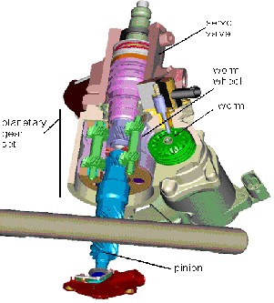
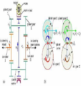
Figure 4: AFS actuator
3 MODEL OF PLANETARY GEAR
Active front steering system is primarily comprised of a rack-and-pinion steering system, a double planetary gear, an electric actuator motor, a worm gear, an electromagnetic locking unit in case of a safety relevant malfunction, and an electronic control unit as brain. The hand steering wheel connects with the sun gear I, the sun gear I meshes with the planetary gears I, at the same time, the motor rotation is transmitted to the planet carrier by the worm gear, then the planet carrier angle couples with the planetary gears I result in the rotation of the planetary gears II, and planetary gears II meshes with the sun gear II, the sun gear II connect with steering gear’s pinion solidly, finally the motion transfers to front road wheels through steering gear and the linkage between steering gear and road wheel. Each planet gear I is jointed to planet gear II solidly, so each planet gear I and planet gear II rotate synchronously, the worm is connected with motor rotor, worm wheel and the planet carrier is integrated into one part, as shown in Fig.5
Figure 5: (a) 3D-model of planetary gear set and electric motor; (b) Structure of planetary gear set.
The worm will be locked if the system is shut down and in case of a safety relevant malfunction. In this case the driver is able to further steer with a constant steering ratio like a traditional steering system. Therefore, the safety of system is certified. Figure .5(b) shows the mechanisms of planetary gear, the core of AFS. The angular velocity of sun gear I, sun gear II, and planet carrier are denoted by 
 respectively. The angular rotation velocity of planet gear is denoted by
  We assume that the angular velocity of sun gear I equal to the hand steering wheel, the angular velocity of planet carrier equal to motor gained by worm gear, and the sun gear II equal to the steering gear’s pinion. The elastic deformation of all the steering linkages and the fluctuation of angular velocity caused by non-constant velocity universal joints are not considered in the model. The above relationship is described as that:


(4)
Where iw denote the ratio of worm gear
Based on analyzing transmission of sun gear I to planet
gear I, and planet carrier to sun gear II, we derived the
relationship among the steering gear’s pinion angle δ v, the
IJSER © 2012
http://www.ijser.org
International Journal of Scientific & Engineering Research, Volume 3, Issue 6, June-2012 5
ISSN 2229-5518
hand steering wheel angle  s, and the electrical motor angle
δ M.
M.

We infer from motion of planet gear I and II two equations:  (
(  )
) (5)
(5)


) (6)


Where ω c denote the angular velocity of sun gear I, ω a the sun gear II angular velocity, ω H the angular velocity of planet carrier, ω p the rotational angular velocity of planet gear, Rc the sun gear I pitch radius, Rf the planet gear I pitch radius, Ra the sun gear II pitch radius, Rg the planet gear II pitch radius.
Equation (7) is derived from (5) and (6)


Ra/Rg
 Rc/Rf
Rc/Rf ω H
ω H Ra/Rg -
  / (7)
/ (7)
Equation (8) is derived from (4) and (7)


 (8)
(8)
The initial state in zero:


 (9)
(9)
It can be inferred from (8) and (9) that:


 (10)
(10)
4 SIMULATION AND RESULT ANALYSIS
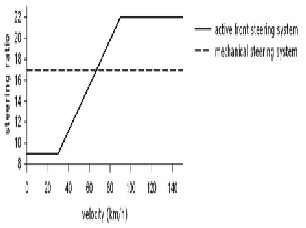
In the paper, we have proposed a simple steering ratio dependent vehicle speed to verify the function of variable steering ratio, as shown in Fig. 6. Steering ratio is divided into three parts, steering ratio is set to minimum  at low speed, steering ratio is set to maximum
  at high speed, steering ratio increase linearly with the speed at normal speed. The steering ratio
  is defined like that:
Figure 6: Velocity dependent steering gear ratio
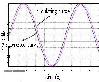
Figure 7: Position Loop of Sinusoidal Input
Tracking Curve
5. CONTROL
5.1 Structure
According to the static equation of gears system, AFS has similar static characteristics with human steering system. Dual planetary gear mechanism as a torque separation device, drivers can predict the percentage of motor driving force in the whole load, the motor overcome the load separated by differential gear train, make the motor rotate to definite position. Actually, Dual planetary gear mechanism is a power assisting device which can reduce load from pinion and rack and make drivers steer lightly. Take the system’s dynamic model as analysis starting point,
IJSER © 2012
http://www.ijser.org
International Journal of Scientific & Engineering Research, Volume 3, Issue 6, June-2012 6
ISSN 2229-5518
the paper designs the whole control system. Figure 8 shows an overview of the control construction.
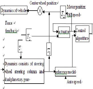
Figure 8: Control Chart of AFS
The system takes an angle generated by steering system as its input, side force of wheels and aligning torque are the responses of vehicle to command. Design a position- tracking control system according to simplified dynamic model of AFS, then the system track reference position in accordance with the driver’s input.
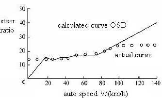
Figure 9: The Relationship between Steering Ratio and Speed
As it is shown in Figure 9, when the car speed is30kmh ,the steering ratio is smaller, this can help to reduce the driver's steering force, thus enhance the steering mobility and flexibility of the system and it is tally with the actual situation; and when the car speed is more than 100kmh ,
system has a bigger, constant steering ratio, this kind of design and characteristics can guarantee that it has excellent steering stability and sensitivity; When the speed changes between30100kmh− , simulation curve coincide with the calculation curve very well. This proofs that AFS adopt dual planetary gear institutions can improve steering sensitivity, there by improve auto’s maneuvering performance.
5.2 Kinematic steering assistance functions
Kinematic steering assistance functions are feed forward controllers which adapt the static and dynamic steering characteristics to the current driving/vehicle situation as functions of the steering activity. This functionality is restricted by the actuator dynamics and the steering feel. These functions are part of the steering system (see Section
4). Currently, the variable steering ratio (VSR) provides the most noticeable benefit for the driver. This kinematic function adapts the steering ratio  , between the steering wheel angle and an average road wheel angle, to the driving situation as a function of e.g. the vehicle velocity (see Figure 10). Under normal road conditions at low and medium speeds, the steering becomes more direct, requiring less steering effort (see Figure 10) of the driver which increases the agility of the vehicle in city traffic or when parking. At high speeds the steering becomes less direct, offering improved directional stability. Additional to the velocity dependency, the variable steering ratio developed by AFS system includes a dependency of the pinion angle i.e. rack displacement. This feature provides a reduced steering effort for large steering angles and a more precise steering for small steering angles. The principle of this function is based on the definition of the steering ratio.
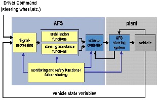
Figure 10: Block diagram including the overall signal flow in the AFS
system
IJSER © 2012
http://www.ijser.org
International Journal of Scientific & Engineering Research, Volume 3, Issue 6, June-2012 7
ISSN 2229-5518
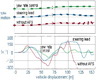
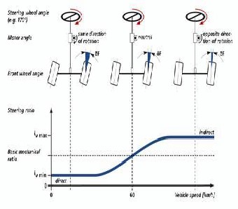
Figure 11: Example of the variable steering ratio as function of vehicle velocity
5.3 Kinematic stabilization functions
The stabilization functions represent another kind of consumer value increment. These functions include closed loop control algorithms that generate automatic steering interventions to stabilize the vehicle (see Figure 12).
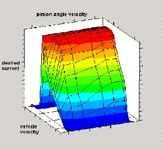
Figure 12: Example of the dependencies of the desired current for the servotronic control
Figure 13: Lane change / ABS-braking with different steering functions
(μ≈0.2)

They are not part of the steering system (see Section 4), they are developed and implemented by the car manufacturer. Some examples of this kind of functions are:
yaw rate control,
yaw torque control and disturbance rejection function.
5.4 Safety and monitoring functions
The above described functions imply high requirements for the safety integrity of the system. For this reason AFS system has developed a suitable safety concept for the steering system that includes several safety and monitoring functions on high and low level.
5.5 System interface

In order to simplify the description of the interface for the modular AFS system, it will be defined in three phases
assistance,
assistance and stabilization and
assistance, stabilization, manual configuration and diagnosis.
The pure assistance interface exclusively includes input signals (I1):
 signed road wheel speeds: input signals of safety and steering assistance functions,
 status of the road wheel speeds: requirement for
utilization of the road wheel speeds,
IJSER © 2012
http://www.ijser.org
International Journal of Scientific & Engineering Research, Volume 3, Issue 6, June-2012 8
ISSN 2229-5518
 steering wheel angle: input signal of a single safety function and several kinematic assistance functions,
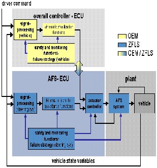
Figure 14: Overall block diagram of the modular system concept
 ESP and ABS intervention flags: binary signal for each road wheel including a brake intervention flag used in safety functions,
 engine revolutions: input signal of the system
dynamic monitoring function,
 current gear: this signal is required only if the sign
of the road wheel velocities is not available,
The interface required for assistance and stabilization
interventions includes besides I1 additional input
signals (I2):
 desired superposition angle for vehicle dynamic
stabilization: input signal which includes a relative superposition angle, represented as an average road wheel angle or pinion angle. This angle is relative to the current absolute assistance superposition angle,
 execute flag of the stabilization intervention:
condition for performing the stabilization intervention. This signal also includes the associated safety information about the intervention command. This interface also includes an output (O2) required by the overall vehicle
dynamics controller and defined by the following signals:
 current average front wheel angle: this signal is computed from the measured pinion angle and the known nonlinear steering kinematics,
 requested steering angle: this angle is computed
from the measured steering wheel angle and the current desired steering ratio, represented as an average road wheel angle or pinion angle,
 desired superposition assistance angle: output
from the kinematic steering assistance functions, represented as an average road wheel angle or pinion angle,
 dynamic capacity: estimated maximal additional
angular speed that can be demanded by an external vehicle controller,
 system status: this signal includes information
about the current system mode (e.g. initialization, on, etc.),
 raw pinion angle: raw signal of the pinion angle
sensor. The receiver of this signal has to perform own plausibility checks. Finally the complete system interface includes the inputs I1 and I2 as well as I3 with the signals:
 VSR flag: signal for switching the mode of the VSR
(e.g. sport, comfort),
 SVT/ECO flag: signal for switching the mode of
the kinetic steering assistance functions (e.g. sport, comfort). The complete interface also includes besides the outputs O1 and O2, the output O3 with the signals:
 current superposition angle: this signal provides a
redundant information that can be used by the overall vehicle dynamics controller for diagnosis/monitoring purposes,
 failure code: this signal includes information about
all failures/errors that are relevant for diagnostics.
6. STATIC STEERING TEST
The performance of static steering mostly represents the convenience of vehicle steering. So the static steering test is a basic test for steering system performance. The steering wheel angle input is two cycles sine of 0.2Hz, 270 degree, as shown in Figure 15(a). Figure 15(b) illustrates the result of static steering simulation. The result shows that front road wheel angle of vehicle with AFS is larger than without, that is to say, AFS turn more directly when static and at low speed. Active front steering system makes the maximum steering wheel angle of the test vehicle decrease from 1.3 to
0.75 turns.
IJSER © 2012
http://www.ijser.org
International Journal of Scientific & Engineering Research, Volume 3, Issue 6, June-2012 9
ISSN 2229-5518
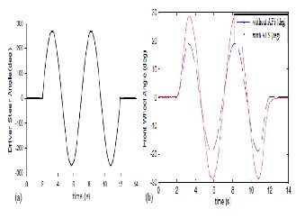
AFS let driver easier to handle particularly on winding path.
Figure 15: (a) Time history of steering wheel angle; (b) Front wheel angle with AFS vs without AFS
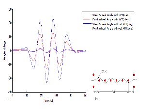
Figure 16: (a) Steering wheel angle and front wheel angle of slalom test; (b) Pylon Markers of slalom test.
6.1 Slalom test
 The slalom test is used for examining the vehicle turning performance at low speed. The pattern of the test road is shown in Fig. 16(b). Pylons space L=36m, vehicle speed is 30 km/h.
 Fig. 16(a) shows the simulation result: In case of slalom test, whether the vehicle assembles active steering system or not, front wheel angle is almost the same, but steering wheel angle of vehicle with AFS is even smaller than without. In this case, vehicles with AFS can cut off the steering wheel angle about 40% at 0-30km/h. So the vehicle with
7. CONCLUSION
By analyzing the structure of Active Front Steering System, the active front steering gear model is completed, which includes the planetary gear model and steering gear model. Taking account of the vehicle steering sensitivity and maneuverability, a simple linear steering ratio is proposed. And a PID controller for variable steering ratio function is designed in Simulink. The simulation tests are carried out in Car Maker to verify the function of variable steering ratio. The results confirm that AFS can improve the vehicle maneuverability especially at low speed. The market introduction of the Active Front Steering system represents an important step towards an entire chassis control in a series vehicle. The high equipment rate of AFS system had to focus on a modular system concept that allows an independent development of assistance and stabilization (vehicle control) functions. Moreover, the enclosure and autonomy of the steering system improves the availability and allows reuse of functions and components for several vehicle platforms. The defined system interface minimizes the application and testing time and costs. The protection of the OEM and supplier know-how is also supported by the modular concept, allowing an overall system integration by a third party.
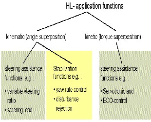
Figure 17: Structure of high level functions
IJSER © 2012
http://www.ijser.org
International Journal of Scientific & Engineering Research, Volume 3, Issue 6, June-2012 10
ISSN 2229-5518
ACKNOWLEDGMENTS
Author would like to thank Dr.Dinesh.N.Kamble (project guide) for guiding and correcting various documents of mine with attention and care. Mr. Sanjay Patil (Assistance Manager Service BMW,pune) He has taken pain to go through the project and make necessary correction as and when needed. A special thanks to Mr. Krishna Kant Mishra
& Mrs. Sabita Mishra, Amrita & Abhishek Kumar For there
great support when author needed. Our colleagues Mayank
Jain, Pratibha Yadav, Rakesh Kumar Singh, Rajesh
Bhandare, Shishir Tripathi, Ankit Bhuptani for their
excellent work developing the assistance and safety functions as well as the failure strategy for the modular concept of "An Overview Of Active Front Steering System"
REFERENCES
[1] Z. Yu, Z. Zhao, and H. Chen, Influences of Active Front Wheel Steering on Vehicle Maneuver and Stability Performance, China Mechanical Engineering, vol. 16, 2005, pp. 652-657.
[2] X. Sun and J. Zhao, Design of Active Front Steering System, Tractor
& Farm Transporter, vol. 35, 2008, pp. 91-94.
[3] J. Guo, J. Li, and Y. Li, Research on Integrated Control of Active Front Steering and Anti-Lock Braking System, Automobile Technology, 2007, pp. 4-8.
[4] Q. Li, G. Shi, Y. Lin, and W. Zhao, Status Quo and Prospect of the Research on Active Front Steering Control Technology, Automotive Engineering, vol. 31, 2009, pp. 629-633.
[5] J. He, D. Crolla, M. Levesley, and W. Manning, Integrated active steering and variable torque distribution control for improving vehicle handling and stability, SAE transactions, 2004, PA 2004-01-1071.
[6] B. Lee, A. Khajepour, and K. Behdinan, Vehicle Stability through
Integrated Active Steering and Differential Braking, SAE 2006 World
Congress, April 2006
[7] C. Deling and Y. Chengliang, Study on Active Front Steering Based on State-space Observer, China Mechanical Engineering, vol. 18, 2007, pp. 3019-3023.
[8] Kirchner, A., Schwitters, F., Vernetzte und modulare Auslegung von Fahrerassistenzfunktionen, VDI – Tagung Elektronik im Kraftfahrzeug 25. Und 26. September, Baden-Baden, 2004.
[9] Klier, W., Reinelt, W., Active Front Steering (Part 1) – Mathematical
Modeling and Parameter Estimation, SAE technical paper 2004 -01-
1102, SAE World Congress, Steering & Suspension Technology
Symposium. Detroit, USA, March 2004
[10] P. Koehn, Active steering-the BMW approach towards modern steering technology, SAE International, vol. 2004, 2004.
[11] W. Reinelt, W. Klier, G. Reimann, and W. Schuster, R, Active Front
Steering(Part 2): Safety and Functionality, SAE 2004 World Congress,
2004, PA 2004-01-1101.

Author
1. Er.Amitesh Kumar (Mechanical Engineer) Masters of Engineering in Automotive Engineering from Sinhgad Academy of Engineering, Pune , India.
E-mail: amitesh.parasar@gmail.com
2. Dr. Dinesh N Kamble (Professor) Mechanical Engineering Dept. at
Sinhgad Academy of Engineering, Pune, India.
IJSER © 2012
http://www.ijser.org


