International Journal of Scientific & Engineering Research, Volume 5, Issue 9, September-2014 163
ISSN 2229-5518
ACCIDENT IDENTIFICATION WITH AUTOMATIC AMBULANCE RESCUE SYSTEM
SRAJAN SAXENA
VIT UNIVERSITY ,VELLORE,INDIA Email:srajansaxena26694@gmail.com
—————————— ——————————
I. INTRODUCTION
There is loss of life due to the delay in the arrival of ambulance to the hospital in the golden hour. This delay is mainly caused by the waiting of the ambulance in the traffic signals. It would be of great use to the ambulance if the traffic signals in the path of the hospital are ON. Thus we pro-pose a new design for automatically controlling the traffic signals and achieving the above mentioned task so that the ambulance would be able to cross all the traffic junctions without waiting. Every traffic junction will have a controller controlling the traffic flow. The traffic junctions are referred to as nodes and each node will have a GSM modem connected to the controller. The nodes are controlled by a main server by sending the control messages to their GSM modems. When a node is controlled and its traffic signal is made to be green for the ambulance to pass through without waiting, it is said to be in ON STATE. For easy access the server maintains a database for each node, and hence each node will have a unique id for addressing it and its GPS co-ordinates are also stored in the database. Thus using these data the ambulance is guided to the hospital by the server through the shortest route.
II. PROPOSED SYSTEM
The system consists of five main units which coordinates with each other and makes sure that ambulance reaches the hospital without any delay. This system is divided into following units
i. Vehicle Unit ii. Main Server
iii. Ambulance Unit iv. Traffic Unit
v. Hospital Unit
In the proposed system, vehicle unit installed in the vehicle that sense the accident. If vehicle met an accident, immediately send the location of the accident to the main server. From the control unit, a message is sent to the nearby ambulance. Control unit finds the shortest route to the accident spot, ambulance, hospital. Also send this path to the ambulance and it transmitted the information to the traffic unit through RF communication. Also, using this information the control unit controls all the nodes in the path of the ambulance and make it ON, which ensures that the ambulance reaches the hospital in time.
IJSER © 2014 http://www.ijser.org
International Journal of Scientific & Engineering Research, Volume 5, Issue 9, September-2014 164
ISSN 2229-5518
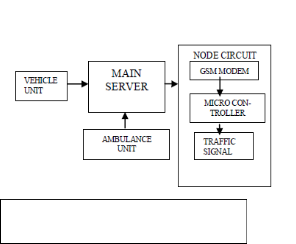
IV. MAIN SERVER
The main server is the central brain of our ITS. It communicates as well as controls every part of the system . The server objectives can be mainly classified into
i. Finding the nearest ambulance to the accident spot ii. Sending coordinates to the ambulance
iii. Controlling the nodes in the shortest path
Fig1 Architechture of proposed system
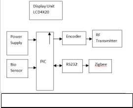
III. VEHICLE UNIT
Each vehicle should have vehicle unit. The vehicle unit consists of a vibration, controller, MEMS sensor, GPS system, GSM module. The vehicle unit installed in the vehicle every vehicle should have a vehicle unit. Thevehicle unit consists of a vibration sensor, controller,MEMS sensor, GPS system and a GSM module. The vehicle unit installed in the vehicle senses the accident and sends the location of the accident the main server. The vibration sensor used in the vehicle will continuously sense for any large scale vibration in the vehicle. The sensed data is given to the controller. GPS module finds out the current position of the vehicle which is the location of the accident and gives that data to the GSM module. The GSM module sends this data to the control unit whose GSM number
is already there in the module as an emergency number.
V. AMBULANCE UNIT
The main server discovers the nearest ambulance to the accident place and also the shortest route between the accident spot, ambulance and the nearby hospital. Then the server sends this path to the emergency vehicle. Ambulance unit also using this information the controller controls all the traffic signals in the path of emergency vehicles and makes it ready to provide a free path to the ambulance, which ensures that the ambulance reaches the hospital without delay. At the same time, the ambulance section turns ON the RF transmitter. This is used to communicate with the traffic department.
Fig 2 Block Diagram Of Vehicle Unit
Fig 3 Block Diagram Of Ambulace Unit
VI. TRAFFIC UNIT
Whenever a traffic signal section receives the information about the accident, the RF receiver in this section is turned ON to search for ambulance nearing the traffic signal. Control the traffic signal automatically with the help of RF module. Whenever the emergency vehicle reaches near to the traffic signal (approximately 100m), the traffic signal will be made of green via RF communication. Thereby the ambulance is recommended to attain the hospital without delay.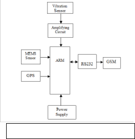
IJSER © 2014 http://www.ijser.org
International Journal of Scientific & Engineering Research, Volume 5, Issue 9, September-2014 165
ISSN 2229-5518
![]()
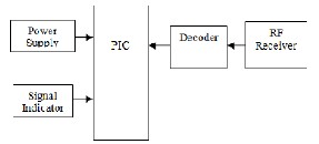
Fig 4 Block Diagram of Traffic Unit
VII. HOSPITAL UNIT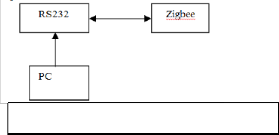
The bio sensor LM35 is used to determine the current condition of the patient like temperature, pressure, and heart beat and that information’s send to the hospital via Zigbee.
Fig 5 Block Diagram of Hospital Unit
VIII. FINDING THE NEAREST AMBULANCE TO THE ACCIDENT SPOT
When a vehicle meets with accident, it immediately sends its GPS location to the Main server. The server maintains a database of the ambulances available. The server selects the nearest ambulance to the accident spot using the database containing the details of free and busy ambulances at that point of time. Then the server scans the locations of the free ambulances in the database. It calculates the distance between the accident spot and each ambulance. Then it compares all the distances calculated and selects the nearest ambulance.
Therefore for performing the above functions, the server must have the following databases:
i. An Ambulance database - contains list of free and busy ambulances at that time.
ii. A NODE database – The Main Server allocates a unique ID for each node and has a database to con-
taining all the nodes’ IDs, GSM numbers and their
GPS co ordinates.
iii. A Hospital database - containing their locations (GPS
coordinates) with their GSM numbers
IX. SHORTEST PATH USING DIJKSTRA
As the nodes in the given region are fixed points and the distance between the nodes are predetermined, the shortest path between the nodes can be selected using the DIJKSTRA algorithm. Consider a case when the ambulance travels from accident spot to the hospital. The database in the server as said earlier contains the node and the distance between the adjacent nodes to which it is connected. The accident spot is taken as the source and the hospital is taken as the destination. The node next to the accident spot and the node in the path to hospital must be traced. So that accident node is taken as source and the hospital node is taken as destination and the DIJKSTRA algorithm is applied for these nodes. There may be several paths between these nodes and the algorithm finds the shortest path. There may be one way roads along this path, therefore this must be a vector quantity. The server finds nearest node from source and marks it as visited. Then that node is considered as source and the procedure is continued till the destination. Initially, the source doesn’t know the distance to destination, so it will be infinite and after complete computation the shortest path along with the distance will be known.
X. SENDING COORDINATES TO THE AMBULANCE
The server will also find the nearest hospital and calculates the shortest path connecting the ambulance’s cur-rent location, the accident spot and the nearest hospital. The shortest path will contain nodes in the path. The server takes the GPS co- ordinates of all the nodes in the shortest path from the NODES database and along with GPS co-ordinates of the accident spot and the hospital.
XI. CONTROLLING THE NODES
A node can possibly operate in two modes namely, the normal mode and the ambulance mode. Normal mode is usual traffic control by a micro controller in a junction. In normal mode, traffic flow in each direction of the mode will be given equal importance . In the ambulance mode, the direction in which the ambulance heads is given importance and is kept in the
IJSER © 2014 http://www.ijser.org
International Journal of Scientific & Engineering Research, Volume 5, Issue 9, September-2014 166
ISSN 2229-5518
ON state, till the ambulance leaves the junction (node). This is done by
i. The node will receive a START SIGNAL from the main server as an control message which contains the direction that must be kept in ON state so that the ambulance can pass through the junction without waiting.
ii. The direction retrieved from the control message is given to the micro controller.
iii. That particular direction is kept in the ON state as long as another message (STOP SIGNAL) is received from the main server.
iv. The STOP SIGNAL is generated when the GPS co- ordinates of the ambulance and the node matches i.e. when the ambulance crosses then node. The node then will return to its normal mode of operation.
XII. INTERRUPT SERVICE ROUTINE ALGORITHM
i. Wait for the reception of the start message along with data
ii. Retrieve the data about the signal to be made green.
iii. Make the corresponding signal to be green
iv. Wait for the reception of next message or signal
v. If the message is received return to the normal mode
By this way each node in the path to the hospital is controlled by the server.
XIII. NODE ACCESS AND CONTROL
The nodes in the shortest path are accessed and controlled only when the ambulance reaches a distance of around say
1km from the node. These locations are stored as the 1km markings. Since the signal should not be kept in ON state for a long time, the node access control is done in the following steps:
i. The server first plots a map with the nodes needed for the shortest path and makes 1km markings for each node.
ii. The locations of 1km markings’ (latitude and longitude) are taken from the map and stored in the NODES data-base.
iii. When the ambulance’s GPS location and location of any one of the 1km markings matches, the corresponding GSM ID with the signal direction from the map is taken by the server and is compared with the shortest path nodes’ GSM IDs.
iv. If that node is present in the path, the START SIGNAL is sent to that GSM ID
v. Now, the node is kept in ON state till the ambulance crosses the node. Once it crosses the node, the server sends a STOP SIGNAL to the node which brings the node to normal mode of operation .
vi. The resolution of the GPS coordinates is that 1 second represents a 101.2ft in latitude and 61.6ft in longitude. Thus in every comparison with respect to ambulance unit, it is enough to note the GPS co- ordinate till the accuracy of second’s.
XIV. CODE FOR CONTROLLING THE NODES
The code below is used for implementing the node control. The ambulance mode is started when an input is got in the C.0 pin of the micro controller from the GSM modem. Consider a signal, similar to message alert in a cell phone, is given to a JK flip flop with its inputs high, so that the output toggles whenever a message is received. Thus when the first message is received, the controller enters into ambulance mode. The data is collected through port D and the corresponding direction is put ON. When the next message is received the controller returns back to the normal mode.
main () // normal mode
{
int i, n, x; Red(0); Red(1); Red(2); Red(3); Green(0); Dela(60); i=0; while(1)
{
n=i mod 4; Yellow(n); Dela(5);
IJSER © 2014 http://www.ijser.org
International Journal of Scientific & Engineering Research, Volume 5, Issue 9, September-2014 167
ISSN 2229-5518
Red(n);
x= (n+1) mod 4; Green(x); Dela(60);
i++;
}
}
// for switching on yellow signal in direction x Yellow(int x)
{
switch(x);
{
case 1:port A0.A1.A2=0;
port A1=1; //yellow light in direction 1 break;
case 2: port A5.A6.A7=0;
port A6=1;
break;
case 3: port B0.B1.B2=0;
port B1=1;
break;
case 4: port B5.B6.B7=0;
port B6=1;
break;
}
}
// for switching on red signal in direction x
Red( int x)
{
switch(x):
{
case 1: port A0.A1.A2=0;
port A2=1; // red signal in direction 1 break;
case 2: port A5.A6.A7=0;
port A7=1;
break;
case 3: port B0.B1.B2=0;
port B2=1;
break;
case 4: port B5.B6.B7=0;
port B7=1;
break;
}
}
// for switching on green signal in direction x
Green( int x)
{
switch( x)
{
case 1: port A0.A1.A2=0;
port A0=1; //green signal in direction 1 break;
case 2: port A5.A6.A7=0;
port A5=1;
break;
case 3: port B0.B1.B2=0;
port B0=1;
break;
case 4: port B5.B6.B7=0;
port B5=1;
break;
}
}
Dela(int z)
{
for(int i=0 ; i<z ; i++)
{
if (C.0==1) /* check for reception of START SIGNAL for every second */
Ambulance ();
Call delay; //1 sec
}
}
Ambulance () //ambulance mode
{
int y= port D; /* port D is input port to get the signal direction to be switched ON for the ambulance*/
Red(1); Red(2); Red(3); Red(4);
switch(y)
{
case 1: Green (1);
break;
case 2: Green (2);
break;
case 3: Green (3);
break;
case 4: Green(4);
break;
}
/*wait for reception of STOP SIGNAL to return to normal mode*/ while (C.0==1)
{
}
}
The ambulance unit has a GPS SYSTEM and a GSM MODEM for transmitting GPS data to the Main Server. The server receives the GPS data sent by the ambulance at lar intervals of time. The server sends the co ordinates of all the nodes’ in the path to the ambulance. The last two nates (Xn-1, Yn-1) and (Xn, Yn) will indicate the accident location and the hospital location respectively. The ambulance unit on receiving the co-ordinates plots them on to a map with the last two co ordinates as the accident spot and the hospital location
to get the shortest path to the hospital.
IJSER © 2014 http://www.ijser.org
International Journal of Scientific & Engineering Research, Volume 5, Issue 9, September-2014 168
ISSN 2229-5518
![]()
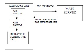
Fig 6 Ambulance Unit Working
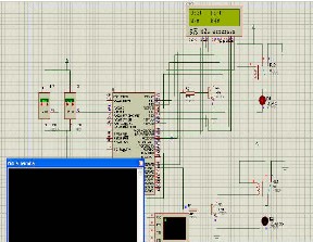
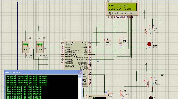
XV. STIMULATED RESULTS
Automatic Accident Detection and Ambulance Rescue with Intelligent Traffic Light System is simulated using PROTEUS SOFTWARE and their results are presented here. The circuit model of the above system is shown and sensors are connected to measure output result.
NORMAL CONDITION: In normal condition the vibration sensor and fire sensor value will be less than the present value.
ACCIDENT CONDITION: If a vehicle has met accident, vibration sensor gives the electric signal to microcontroller through signal conditioner. Then GPS provides latitude and longitude information about vehicle location to control section through GSM.
FIRED CONDITION: If a vehicle has met accident, fire sensor gives the electric signal to microcontroller through signal conditioner. Then GPS provides latitude and longitude information about vehicle location to control section through GSM
IJSER © 2014 http://www.ijser.org
International Journal of Scientific & Engineering Research, Volume 5, Issue 9, September-2014 169
ISSN 2229-5518
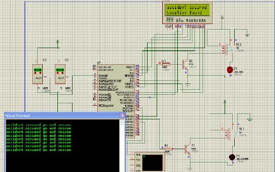
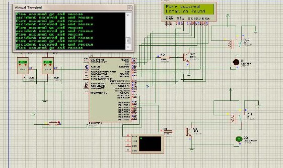
BEFORE AMBULANCE REACHING TRAFFIC SIGNAL: Before ambulance reaching the traffic signal junction, the signal will be red. Control section transmits the control signal to all the signals in between ambulance and vehicle by RF transmission.
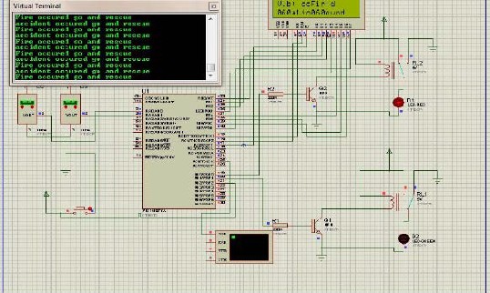
AFTER AMBULANCE REACHING THE TRAFFIC SIGNAL: After ambulance reaching the traffic signal junction the signal will turn into green with the help of the RF signal.
IJSER © 2014 http://www.ijser.org
International Journal of Scientific & Engineering Research, Volume 5, Issue 9, September-2014 170
ISSN 2229-5518
XVI. CONCLUTION: In this paper, a novel idea is proposed for controlling the traffic signals in favor of ambulances during the accidents. With this system the ambulance can be maneuvered from the ITLS can be proved to be effectual to control not only ambulance but also authoritative vehicles. Thus ITLS if implemented in countries with large population like INDIA can produce better results. The ITLS is more accurate with no loss of time. But there may be a delay caused because of GSM messages since it is a queue based technique, which can be reduced by giving more priority to the messages communicated through the controller.
XVII. REFERENCES
[1] Qingfeng Huang and Ying Zhang. “Dynamic balancing of push and pull in a distributed traffic information system.” In
IEEE Consumer
[2] Xu Li, Wei Shu, Minglu Li, Hong-Yu Huang, Pei-En Luo, Min-You Wu, “Performance Evaluation of Vehicle-Based Mobile
SensorNetworks for Traffic Monitoring” IEEE transactions on vehicular technology, May 2009, vol. 58, no. 4, pp. 1647-1653.
[3] Xu Li, Wei Shu, Minglu Li, Hong-Yu Huang, Pei-En Luo, Min-You Wu, “Performance Evaluation of Vehicle-Based
Mobile Sensor
Networks for Traffic Monitoring” IEEE transactions on vehicular technology, May 2009, vol. 58, no. 4, pp. 1647-1653.
[4] Jianhou Gan, Lingyun Yuan, Zhongqi Sheng and Tianwei Xu, “Construction and Implementation of an Integrated WSID Traffic Monitoring Network System”, Proc. 21st annual international conference on Chinese control and decision conference,
2009, pp. 4726-4731.
[5] A novel simulation of AC magnetic contractor based on electromagnetic transients program (pages144-150) .IEEJ transactions on Electrical and Electronics Engineering
IJSER © 2014 http://www.ijser.org
International Journal of Scientific & Engineering Research, Volume 5, Issue 9, September-2014
ISSN 2229-5518
171