International Journal of Scientific & Engineering Research Volume 3, Issue 8, August-2012 1
ISSN 2229-5518
A Simple Real-Time People Counter with Device
Management System Using Digital Logic Design
Sani Md. Ismail, Shaikh Mohammad Fahim, Mahmood Reaz
Abstract— In this paper, we have developed a simple but totally real time people counter along with an automated device management system controlled by a digital circuit for ensuring proper power consumption. We have assumed a certain scenario by consideri ng a particular space with predefined room capability , where not only the people’s entrance in that room is co ntrolled by a counter and sensor system but also the room’s several electronic devices are controlled by a digital block circuit according to the number of pe ople present in that room.
Index Terms— device management system, digital system, real-time operation, people counter, power consumption, sensors, subtractor
—————————— ——————————
1 INTRODUCTION
OWER consumption is of high concern at present in the whole world. Technologies are being developed to ensure the least power consumption possible. In general, we are
responsible for wasting power in various ways. Frequently we
forget to switch off lights and fans in our room when we go out. Sometimes, we are too lazy to do that. So, what if we de- sign a system for saving energy where the system will auto- matically detect whether the room is empty or not and how many people are in the room with the help of sensors and counter system and will control the lights, fans, air condition- ers and other necessary electronic equipment according to the presence of people in the room [1]. We have developed that kind of a system for a particular space (e.g. hall room, library, conference room, laboratory, train compartments, waiting rooms, museums etc.). According to our design, the number of people present in that space will be counted by sensors and sequential logic system and the various electronic devices and instruments (lights, fans, cooling systems, laboratory equip- ment etc.) will be controlled by a combinational logic system according to that number of people. Sometimes, in many cas- es, all devices and equipment in a place aren’t used by the people present there. A certain number of people need a cer- tain amount of devices. So, our system will detect the number of people in a space in completely real time basis and activate the number of devices according to the number of people. When there is no person in that space, all the equipment will be turned off electronically. These electronic equipment will be automatically controlled by a designed digital block circuit (combinational logic system).
Most of the people counter systems are based on various
image processing techniques. Most of these techniques are quite complex and critically designed to achieve very high accuracy. These systems require vast memory storage in order to process images properly and accurately. Some process con- sists of various bindings which can be very serious and inef- fective for some applications although they provide very high accuracy. One process is image sequence analysis using mor- phological tools [2] with less than 2% error rate. It denies background subtraction techniques for variation in illumina-
tion and weather. But the most important fact is-it is not com- pletely real time process rather it is a delayed-real-time process [2] which can be ineffective for various applications where real time operation is a prime concern.
Multi sensing application [1] process is quite effective people counting process which requires fabrication of ceramic type pyro electric array detector along with various algo- rithms (e.g. background mean method, differential detecting method etc.). This method provides 95% accuracy. But all kinds of image processing techniques require complicated design and availability of adequate memory storage.
Unlike image processing techniques, our system is very
simply designed which doesn’t only count people in a space
but also control device activation according to the number of
people there without any requirement of vast memory sto- rage. This system is dependent on the sensors which will detect the movement through the door. Although these sen- sors have comparatively low accuracy rate [1], but this disad- vantages can be eliminated by improving the type, position, quantity and parameters of the sensors.
2 PARTICULAR SCENARIO AND ASSUMPTIONS
We have assumed a scenario of a particular space (e.g. hall room, library, conference room, laboratory, train compart- ments, waiting rooms, museums etc.) which can accommodate
30 people. Our system will control the entrance of people in that space according to the number of people already present there. When 30 people are in the space, the entrance in the
room will be terminated temporarily. When the space has less than 30 people, then entrance system will be re-activated and the system will show how many people can enter there at that time.
We will also control the activation of electronic devices (e.g.
lights, fans, cooling systems etc.) available in that space ac- cording to the presence of people. We have defined a protocol which describes how many groups of electronic devices will be activated according to the number of people there. Imagine there are 6 groups of electronic devices (A, B, C, D, E, and F).
IJSER © 2012
http://www.ijser.org
International Journal of Scientific & Engineering Research Volume 3, Issue 8, August-2012 2
ISSN 2229-5518
Each group consists of a number of various electronic devices. A particular number of people need a particular number of devices. The protocol is described in the following table 1 con- sidering existence of 0 to 30 people in that space.
TABLE 1
GROUP/S OF ELECTRONIC DEVICES ACTIVATION PROTOCOL
We have applied some other conditions for this system that should be strictly followed. These conditions are:
1. Entrance and exit gates should be different,
2. More than one person should not pass through any
one gate at the same time,
3. Passing through any other medium is restricted.
There can be more than one entrance and exit gates
and only these gates should be used for entering and
leaving,
4. Entering through exit gate and leaving through en-
trance gate are strictly prohibited.
According to the above described rules, regulations and conditions, our system will detect number of people in a par- ticular space, decide how many people should enter further and control the activation of electronic devices available in that space.
3 SYSTEM OPERATION AND DESIGNS
Our system operation has been illustrated in figure 1. Descrip- tions of some of the segments are given below:
Figure 2 and 3 show modified 5-bit positive edge triggered asynchronous counters [4] used in entrance and exit gate.
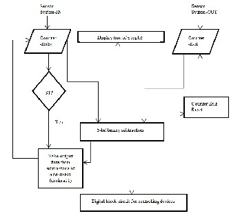
Fig. 1. Flowchart describing the total operation of the system
Fig. 2. Entrance gate counter system
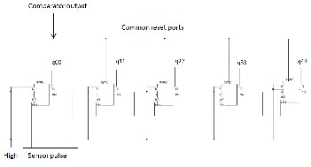
3.1 Counter and Sensor System
We have used modified positive edge triggered counter sys- tems for counting the number of people present in the space. We have used two sensor systems (e.g. IR sensors, motion sen- sors, light sensors etc.), one at entrance gate and another at exit gate. The sensors will generate a pulse when someone passes the door and the pulse will be sent to the correspond- ing counter systems as clock pulses. The pulses needed to be shaped according to the operating frequency of counters. The counter system at entrance gate will count how many people are entering into the space. The counter system at exit gate will count how many people are leaving the space.
IJSER © 2012
http://www.ijser.org
Fig. 3. Exit gate counter system
International Journal of Scientific & Engineering Research Volume 3, Issue 8, August-2012 3
ISSN 2229-5518
3.2 5-bit Subtractor System
We have used a 5-bit binary subtractor [3] system that will take the outputs of both counter systems (q0q1q2q3q4 and q00q11q22q33q44) mentioned above as inputs and provide the subtracted value of these two inputs which indicates how many people are present in the space at that time. The output of the subtractor will be fed to a display system which will show the number of people present in the space at the en- trance gate.
The output of the subtractor system is linked with entrance gate counter system. We have developed this system in such a
way that the output of the comparator will control the value stored in two counter systems.
3.3 Comparator System
We have used a comparator system [3] which has a default input 11111 (31 in decimal) and another input which is fed from the output of the entrance gate counter system. When the entrance gate counter system output is 31, the comparator will generate high at its output and it will deactivate the entrance gate counter system and load the output of the counter (q0q1q2q3q4) manually like a parallel load register [4]. This will store the value of the subtractor output added 1 to the entrance gate counter system (working as parallel load regis- ter). Also high state in the output of comparator will reset the exit gate counter system.
This process has been developed to control the number of bits of the operation. We have used 5-bit comparator, subtrac- tor and counter system (as maximum 30 or binary 11110 people are allowed in the space). So, it is very important that all processing values are of 5-bit value. But we have found a number of scenarios where the output of the counter logically exceeds the number of bit 5. Assume that if a total of 30 people enter and no one gets out, the number of people in the space will be 30 and the entrance counter stores 30. Suddenly 20 people leave the space, the number of people in the space will be 10 and 20 more people will be allowed in the space. But in the meantime the entrance counter system has kept the value
30 stored. Now if 20 people want to enter the room, who are
logically valid to enter, the entrance counter system needs to
count 20 more. But, that will exceed 5-bits. Obviously a 5-bit
counter system cannot count the number more than 5 bits. So,
in that case, the counter will begin counting from 0, which will be unacceptable and wrong operation. So, we have developed the system in such a way that the number of bits in the whole operation will remain 5 without any fault. When the counter counts 31 (after counting 30), the entrance gate counter system value will be replaced by the output of the subtractor system added 1 (5-bits value+00001) and it will reset the exit gate counter system. Recalling the previous scenario (30 people are in, suddenly 20 people are gone), when next person will enter the room, value stored in counter will be 31. Then according to logic, the entrance gate counter system will store (10+1) = 11 (1 is added because last entered person needs to be counted). The exit gate counter system will be reset by that clock pulse giv- ing the output of the subtractor 11, which is the exact number
of people in room at that moment. The linkage between com- parator and counter system is shown in figure 2 and 3.
3.4 Display Devices
Display system at the entrance gate will show how many people are in the space and how many more are allowed to enter into the space.
3.5 Selection of Groups of Electronic Devices for
Activation
A digital block circuit system will control the activation of devices according to the number of people following the de- scribed rules in Table 1.
Fig. 4. Digital circuit system for selection of groups
Fig. 4 shows the digital block circuit we have designed for selecting various groups of electronic devices. This circuit has been designed in ALTERA QUARTUS software according to the following equations:

“P0P1P2P3P4” is the 5-bit output of the subtractor and A, B, C, D, E, F are 6 groups of electronic devices we have assumed. Activation of these groups is dependent on the subtractor out- put according to the relations described in above six equations (equation (1)-(6)).
IJSER © 2012
http://www.ijser.org
International Journal of Scientific & Engineering Research Volume 3, Issue 8, August-2012 4
ISSN 2229-5518
4 SIMULATIONS
We have simulated all the counter system operations in AL- TERA QUARTUS software using Verilog HDL code [5]. The simulation of the device management system has been done in same software using schematic simulation process
Figure 5 illustrates the simulation of the counter system we
have designed. In the simulation, “Clk1” and “Clk2” denote
the two sensor pulses in two gates. “Entry” and “exit” tab
represents the stored data in the two counter systems. It is seen that according to the applied logic, the subtractor (“people” tab in the simulation) is providing the number of people in the space accurately.
Figure 6 demonstrates the real time operation of the system.
We have run a simulation regarding a scenario where one per- son is entering into the space and at the same time another person is leaving the space. We have to observe whether the system is providing flawless information about the total num- ber of people in that space during this particular scenario. We have run the simulation of this scenario not one time, rather six consecutive times (from the marked position in the simula- tion) and the system is providing us flawless smooth informa- tion that there are 24 people in the space. Clk1 and Clk2 are providing positive edge at the same time which means two persons are entering and leaving at the same time, so the overall number of people in the space (“people” tab in simula- tion) is remaining constant. The last two tabs, “result1” and “result2” are showing the value stored in two counter systems instantly. “result1” denotes entry gate data and “result2” de- notes exit gate data. The subtractor system is providing real- time correct information about the number of people in the room, taking “result1” and “result2” as inputs. This simula- tion is the perfect evidence of the real-time characteristics of this system.
Figure 7 illustrates the simulation of the digital block circuit
system or device management system. This simulation has been done in ALTERA QUARTUS using schematic simulation process. According to the logic implemented in Table 1, the 6 groups (A, B, C, D, E, F) are activating according to the number of people (subtractor output: P0P1P2P3P4) present in the space. When, the room is full, all the six groups of devices are electronically activated. The groups are de-activated according to the number of people in that space. When there is no one in the space, all the devices are turned off automatically.
Figure 8 illustrates the simulation of the parallel in parallel
out register system after the entrance gate counter counts 31 (marked position). When it counts 30 (“entry” tab), the room has 19 people (“people” tab) in it so 11 more people are allowed to enter the room. When the next person enters, the counter counts 31 and this value is replaced by (19+1) =20 counting the last person just entered.
The exit gate counter system is reset storing the value 0,
providing the data that there are 20 people in the space which
is the correct value. After this scenario, the system will run in
normal mode and repeat the same process when the entrance
gate counter counts 31 again. It is clear from the simulation that the system is working flawlessly at any kind of logical situation, providing real time data.
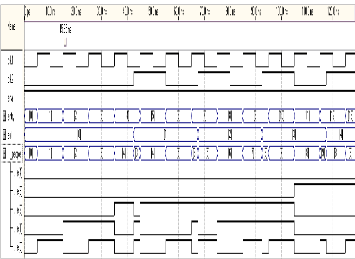
Fig. 5. Simulation of the counter system
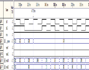
Fig. 6. Real time operation of the proposed system
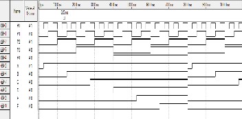
Fig. 7. Device activation according to the implemented logic
IJSER © 2012
http://www.ijser.org
International Journal of Scientific & Engineering Research Volume 3, Issue 8, August-2012 5
ISSN 2229-5518
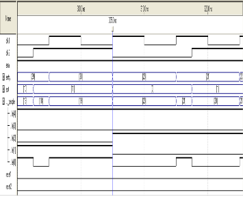
Fig. 8. Simulation of the parallel in parallel out register system after entrance gate counter counts 31
5 CONCLUSION
The people counter we have designed is based on digital cir- cuit design therefore memory requirements due to this system are quite low. Sensors used for this system need to be estab-
lished and placed very carefully so that it gives flawless sig-
nals about the movement of the people. As it is a completely real time process, so real time operations support this system. We can eliminate some assumptions we have made to operate this system by improving the sensing elements to a whole new advanced level.
This system is also design for ensuring proper power con-
sumption which is very important for us to save our energy. The device management system described here is an auto- mated activation system of devices designed for avoiding power wastage and ensuring proper power consumption. Electronic activation of devices is of great concern today and can be used in this system very effectively.
We have described the system for 5-bit operation. For dif-
ferent bit system operation, (for example, if the room can ac- comodate 10 or 100 people) we need to design both hardware and logical terms differently. But if we use micro-controller in
this system, we just have to reprogram the system according to our requirements. So, this system can be taken to a tre- mendous efficiency level by further proper supervision.
REFERENCES
[1] Hashimoto, K., Morinaka, K., Yoshiike, N, Kawaguchi, C. And Mat- sueda, S., People Count System Using Multi-Sensing Application, 1997
International Conference On Solid State Sensors And Actuators,
1997. TRANSDUCERS '97 , Chicago, 2, JUN 1997, 1291-1294 (Confe- rence proceedings)
[2] Albiol, A., Mora, I. And Naranjo, V., Real-Time High Density People Counter Using Morphological Tools, IEEE Transactions on Intelligent Transportation System, 2(4), DEC 2001, 204-218 (IEEE Transactions).
[3] M. Morris Mano, Digital Logic and Computer Design (Prentice Hall, Inc., 1979, Edition: 2008) (Book Style).
[4] Thomas L. Floyd, Digital Fundamentals (Pearson Education, Inc., 2003, Edition: 2009-2010) (Book Style).
[5] Stephen Brown, Zvonko Vranesic, Fundamentals Of Digital Logic With Verilog Design, Tata Mcgraw-Hill Companies, Inc., 2008, Edition: Spe- cial Indian Edition 2007) (Book Style).
————————————————
 SANI MD. ISMAIL is graduated in B.Sc. in Electrical Electronic and Com- munication Engineering from Military Institute of Science and Technology, Bangladesh University of Professionals, Bangladesh, currently employed as system engineer at Sarah Composite Mills Ltd., GREEN GROUP of INDUS- TRIES, Bangladesh. PH-8801711649435. E-mail: sani_bd_786@yahoo.com, sismail@sarah.com.bd
 SHAIKH MOHAMMAD FAHIM is graduated in B.Sc. in Electrical and
Electronic Engineering from Islamic University of Technology, Bangladesh, currently employed as a lecturer at PRIME ASIA UNIVERSITY, Bangladesh.
PH-8801715268233. E-mail: sfahim88@yahoo.com
 MAHMOOD REAZ is graduated in B.Sc. in Electrical and Electronic Eng i-
neering from American International University Bangladesh, currently sch e- duled to begin Masters Degree in Electrical Engineering (Smart-grid) at Tam-
pere University of Technology, Finland from August, 2012. PH-
8801717792906, E-mail: mahmood_reaz@yahoo.com
IJSER © 2012
http://www.ijser.org