International Journal of Scientific & Engineering Research Volume 4, Issue3, March-2013 1
ISSN 2229-5518
A SIMPLE CLOSED LOOP DC MOTOR SPEED CONTROL SYSTEM
ON FPGA PLATFORM FOR VHDL BEGINNER
Prof. Shashank Pujari
Sambalpur University Institute of Information Technology(SUIIT), Burla, Odisha, India pujarishashank@gmail.com
Abstract – Students develop interest to understand the theory around a project that fascinates them. The motivation of this paper has been to devise a model for teaching VHDL language to embedded students. The teaching model is based on a practical example of a simple DC Motor control application conducted in the lab session. A series of Lab modules from basic digital logics leading gradually to a closed loop DC motor speed control is presented as lab experiments to maintain the interest of first time learner of VHDL language. The theory of VHDL language construction is covered separately by way of classroom lectures but in conjunction with the Lab practice sessions.
Index Terms— VHDL, FPGA, MOTOR, LEARNING MODEL
—————————— ——————————
1. INTRODUCTION
Learning VHDL language is a subject of interest to students pursuing program in VLSI and Embedded System Design. Learning of any languages including ‘C’ are delivered universally through theory based classroom sessions along with associated hands on session in the lab-supported assignments. Programming Language based subjects could be 4 credits Lecture and 2 credit Lab. Universally it is accepted as a fact that “If we hear, we forget; if we see, we remember; if we do, we understand“. To make learning fun and develop interest in students, labs are based on real life applications. This paper covers a step-by-step guide in building a simple application for embedded students in VHDL Lab sessions. Embedded students are more close to Microcontroller based design and control applications. Present paper covers VHDL language learning with lab sessions based on a FPGA based simple DC motor control application.
The paper is organized as follows; in section II VHDL Language as theory is introduced. VHDL Theory lectures are followed by corresponding LAB sessions which are explained in section III with the gradual building of modules towards implementing the DC Motor control application. Observations are tabulated in section IV. Concluding remark and extending the scope of the paper is given in section V.
————————————————
Prof. Shashank Pujari is currently at Sambalpur University Institute of
Information Technology,Odisha, India. E-mail: pujarishashank@gmail.com.
2. THEORY INITIATION
The objective of learning VHDL is to prepare students understand HDL structure and to write VHDL coding for a given functional block. Students are expected to have knowledge of basic Digital Logic System Design. The course begins with foundation lecture on combinational and sequential logic to refresh students and bring them all to same level than moving on to basic constructs, types of modeling i.e., Behavioral Modeling, Data Flow & Structural in VHDL, data types and operators. The course extends to Combinational logic, Arithmetic function, Encoders, Decoder, Comparators, Multiplexor, Tristate buffers. Flip Flops, Shift Registers, Counters and state machines etc.
The course further covers synthesis issues and writing synthesizable HDL codes and testing on targeted CPLD/FPGA to implement a complete system.
During the course, implementation of hardware drivers for basic peripheral devices such as LED, SWITCH, KBD4X4, STEPPER MOTOR, ADC, DAC, LCD, UART etc. and specifying the constraints of signal pins, timing to remove setup and hold violation and proper implementation on the target device are covered.
3. LAB INITIATION
VHDL Labs should start after few classroom lectures on VHDL. Labs should be planned in advance and made result oriented. Students should be asked to install VHDL synthesis and simulation tools individually.
IJSER © 2013 http://www.ijser.org
International Journal of Scientific & Engineering Research Volume 4, Issue3, March-2013 2
ISSN 2229-5518
Many Vendors of Programmable Logic such as Xilinx, Altera, Actel and host of others provide their free tools downloadable from respective sites on net
Xilinx synthesis tools ISE12.0 has been used in carrying
SPARTAN 3 FPGA
1 sec
clk 7 seg
display
A
F B
out the Lab experiments. Students do self-practice in the
usage of the tool by following the Quick start guide from
Help menu of the tool.
VHDL is a highly syntactic and structural language. It is often observed that students make mistakes in writing VHDL code with wrong syntax even if they have the idea of the various abstraction levels of VHDL based Logic design and FPGA design tool flow.
The quick start guide has a design example of a counter, which forms the basis of starting the Lab experiments. In this process they learn the usage of the tool and become
50
MHz clk
Sw
1
Sw
2
Sw
3
26 bit
counter
speed setting
BCD
counter
compar ator
E C D
equal greater
lesser
familiar with the FPGA design flow. Students are asked to enhance the counter design example.
The design of a Synchronous, Resetable, Up/down counter is taught and the use of switch, LEDs and clock is learnt. The counter design is changed to a 8 bit shifter to do left or right shift through switch.
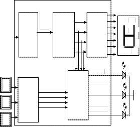
Fig – 2, BCD counter, a 7 segment display decoder and a comparator for display and compare with set input.
Figure 3 shows extension and variation of last module. An external clock now drives the 4-bit BCD counter. A clock enable of duration 1 sec is introduced which is generated by a 24-bit counter. So the 4 Bit BCD counter samples the external clock at the rate of 1 sec. At the end of
1 sec the BCD count value is stored in the following 4 Bit
SWITCH
50 MHz
SPARTAN 3 FPGA
1 SEC CLK
8 BIT
LED
register. The stored 4-bit BCD value is displayed on a 7- segment display as well as compared with three-switch value assigned to three different values in the range 0 to 9, say 3, 6 and 9. LEDs display the comparator outputs.
CLOCK VCC
SWITCH
26 BIT
COUNT ER
UP/DN CONTROL
COUNTER
/
SHIFTER
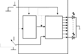
Figure-4 shows the motor driver unit. PWM control logic
is used to regulate the speed of the motor. The duty cycle of
the PWM is controlled by the output of a UP/DN counter,
which in turn driven by the comparator for counting UP or
DOWN. The comparator as shown in earlier Figure-3
compares the set value against the sampled BCD count
value. The DC motor driver is a two-stage transistor circuit
to supply suitable current to the motor. When the low
Fig - 1, 26bit counter to generate a 1 sec slow clock which drives the following 8 bit counter. This makes the display of the counter output value visible on LEDs. The counting direction of the counter is controlled by an external switch input.
The 8 bit counter is extended as two 4 bit BCD counters. The output of these counters is displayed on two 7 segment display and also passed to a comparator. Case statements are introduced in VHDL code to realize 7 segment display and comparator.
power switching transistor BC-457 is OFF the high power transistor SL-100 is ON and the motor gets supply current and rotates. Hence the PWM pulse needs to be reversed so that ON period of PWM decides the motor ON period. The average voltage decides speed of the motor. The IR LED based speed encoder generates pulses in proportion to the rotation of the motor. The speed encoder is made out of a wheel with 8 holes. So the IR transmitter/receiver LED generates 8 pulses per one revolution of the motor.
IJSER © 2013 http://www.ijser.org
International Journal of Scientific & Engineering Research Volume 4, Issue3, March-2013 3
ISSN 2229-5518
All the blocks of Figure 3 and Figure 4 are combined together resulting in a simple closed loop DC motor control system. The UPDN counter driven by the PWM generator is also included in FPGA fabric. The single 4-bit BCD counter is extended to two 4-bit BCD counter and its registered output is displayed on two 7-segment displays. This is done to display the two digit speed value of the motor encoder pulses sampled per one sec.
4. IMPLEMENTATION & OBSERVATION
The design was tested using Xilinx Spartan3 KIT having XC3S200 device as shown in Figure 5 in Lab setup. Modelsim simulation was used to simulate all modules individually.
IJSER © 2013 http://www.ijser.org
International Journal of Scientific & Engineering Research Volume 4, Issue3, March-2013 4
ISSN 2229-5518
Table-1 shows the PWM duty cycle and the speed of rotation of the motor in open loop speed control. As seen the motor fails to start at low ON period since the average voltage across motor is not sufficient to overcome the stall inertia.
TABLE – 1
PWM duty cycle versus Motor speed in open loop speed control
Counter Output | Total time (µ sec) | On time (µ sec) | Off time (µ sec) | Speed Pulses per sec |
0000 | 160 | 10 | 150 | - |
0001 | 160 | 20 | 140 | - |
0010 | 160 | 30 | 130 | - |
0011 | 160 | 40 | 120 | - |
0100 | 160 | 50 | 110 | - |
0101 | 160 | 60 | 100 | 06 |
0110 | 160 | 70 | 90 | 08 |
0111 | 160 | 80 | 80 | 12 |
1000 | 160 | 90 | 70 | 14 |
1001 | 160 | 100 | 60 | 17 |
1010 | 160 | 110 | 50 | 20 |
1011 | 160 | 120 | 40 | 22 |
1100 | 160 | 130 | 30 | 25 |
1101 | 160 | 140 | 20 | 27 |
1110 | 160 | 150 | 10 | 29 |
1111 | 160 | 150 | 10 | 29 |
Table-2 shows the closed loop speed control. The difference between set and actual speed is 8 rps. This positive error accounts for maintaining the PWM duty cycle to match the set speed.
TABLE – 2
Reference speed versus actual speed
In Closed loop speed control
Speed Setting | Actual speed Sampled at 0.5 sec | Actual speed Sampled at 1 sec |
10 | 9 | 18 |
16 | 12 | 24 |
20 | 14 | 28 |
The speed encoder pulses found to be noisy at edges due to wobbling of the encoder wheel resulting into false counting of the sampled speed. State machine based debounce logic was introduced for clean counting of motor speed encoder.
5 CONCLUSION
A simple DC motor control application was considered for teaching VHDL language in lab practical. The VHDL
coding, synthesis, simulation and implementation of various modules such as counter, 7-segment display, comparator, PWM generator on Xilinx Spartan-3 FPGA was presented to build the motor control application. Students were made to form group and built different modules, which were then integrated at the end to develop complete system. The case study satisfied the objective of learning VHDL language by beginner in a practical way.
Students can be encouraged to carry out advance study and research on DC motor control by going through papers published in various journals.
The simple DC motor control project can be extended to study the stability issues of the motor control. The sampling duration of the motor speed and the PWM cycle period decides the closed loop control response. The scope of the project can further be extended by inclusion of a PID controller in FPGA after finding out the mechanical and electrical time constant of the DC motor. The motor driver circuit can be made more robust using L29X family devices for bi-directional control of the motor.
6 REFERENCES
[1] www.xilinx.com
[2] VHDL - By Douglas Perry
[3] Fundamentals of Digital Logic with
VHDL Design- Brown/Vranesic
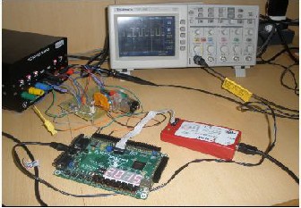
Fig – 5, Lab setup

Prof. Shashank Pujari currently is the director of Sambalpur University Institute of Information Technology. His area of interests is FPGA based Embedded System Design.
IJSER © 2013 http://www.ijser.org