
INTERNATIONAL JOURNAL OF SCIENTIFIC & ENGINEERING RESEARCH, VOLUME 4, ISSUE 9, SEPTEMBER-2013
ISSN 2229-5518
A New Modified Embedded Zerotree Wavelet
Approach for Image Coding (NMEZW)
Nizar Mohammed Ameen Ahmed, Adnan Mohsin Abdulazeez Brifcani
Abstract In this paper, a new modification on the well-known Embedded Zerotre Wavelet algorithm (EZW) is proposed. The EZW is an important embedded wavelet based image coding algorithm, it encodes the image wavelet coefficients by importance. The New Modified EZW (NMEZW) approach exploits the main classification rules used in EZW and Modified EZW (MEZW) presented in 2008. The new modification distributes the entropy among eight symbols instead of four in EZW and six in MEZW. Also, the generated symbols are binary regrouped before entropy coding, which is an additional pass implemented in MEZW too. NMEZW Image coding results are compared to those obtained by EZW, MEZW, SPIHT and SPIKE algorithms.
Index Terms— Arithmetic Coding, Binary Regrouping, Discrete Wavelet Transform, Embedded Coding, Entropy Coding, EZW, Image
Decomposition, MEZW, Morton Scan, Raster Scan, Zero Pair, Zero Triple, Zerotree, Zerotree Brotherhood Relationship.
—————————— ——————————
he main issue which has to be considered in digitized images is their large sizes and their qualification with storage and telecommunication channels. However,
many compression techniques have been introduced in this
First, the grayscale image is decomposed by using the two dimensional Discrete Wavelet Transform (DWT) into multiple
IJSER
field; each has its specifications that qualify specific
requirements. In image compression field, images are coded
either as lossy, where the decompressed data is approximate
copy from the original data; or as lossless in which the
decompressed data is the same copy of the original source data. In lossy compression, a progressive coding means that
the compressed data represent a partial copy of the image data, it also allows stopping coding at any point in order to produce an acceptable reconstructed image to human visual system [1].
The EZW is an attractive progressive algorithm that generates a group of coding symbols using several rules among wavelet coefficients based on zerotree concept, which in return reduces the number of entropy coded symbols.
Many literatures era published in this concern; proposgni
modifications on the original EZW, attempting to improve the
EZW algorithm in different aspects [1], [2], [3], [4].
In this paper, a new modification is proposed, the New
Modified Embedded Zerotree Wavelet (NMEZW), adds new relationships among the wavelet coefficients to generate less number of symbols to be arithmetically coded.
subbands at multiple levels [1], [5], [6]. The wavelet
decomposed image is represented by tree structure, because of
the subsampling that resulted by the transformation [7], [8],
[9]. A coefficient in a lower subband has four children
descendants in the next higher subband. Each child also have
four descendants in the next higher subband and so on, which
makes groups of quad trees, with every root having four leafs
,as shown in the fig.1.
————————————————
Adnan Mohsin Abdulazeez Brifcani – President of Duhok Polytechnic
University, Duhok, Kurdistan, Iraq, E-mail: adnan_brifcani@yahoo.com
Fig. 1. Zerotree Structure and Parent-Child Relationship
IJSER © 2013 http://www.ijser.org
INTERNATIONAL JOURNAL OF SCIENTIFIC & ENGINEERING RESEARCH, VOLUME 4, ISSUE 9, SEPTEMBER-2013
ISSN 2229-5518
If a coefficient and all its descendants scanned and found insignificant with respect to the current threshold, the whole group will be represented by a single Zerotree symbol. Furthermore, each coefficient in the lowest subband (LL3) has
3 spatially children, in the HLn, LHn and HHn subbands respectively [1], [2]; this relationship is called Parent-Child relationship.
The EZW wavelet based image coding approach has proposed by Shapiro J. at 1993 [2]. It uses a fully embedded coding algorithm to represent a sequence of binary decisions by distinguishing significant components from null ones. The EZW algorithm enables the encoder and the decoder to stop the encoding process at any point; thereby allowing a target rate to be met exactly. The coefficients are classified for significance into four types of symbols before they entropy coded. However the next modification the Modified EZW (MEZW) which has proposed at 2008 by Ouafi & et al.[10], [11],[12], redistributes the entropy on six types of symbols instead of four in EZW, it adds two new signed tree symbols, the symbols then binary regrouped to reduce number of entropy coded symbols, that is for achieving specific metric
[12]. The EZW Encoder Block Diagram is shown in Fig .2.
Dominant List: contains significance information concerns the scanned wavelet coefficients.
Subordinate List: contains the amplitude values of the significant found coefficients ordered according to their appearance.
Finally, at the end of coding process, both the Dominant and the Subordinate obtained symbols will be arithmetically coded. The image wavelet coefficients are scanned according to the raster scan scheme, Fig. 3 shows two scan schemes raster and morton.
Fig. 3 Raster and Morton Scan Schemes

Two main passes are used in each iteration, Dominant Pass and Subordinate Pass. During the Dominant Pass the coefficients are scanned according to the predefined scan path for significance mapping. In EZW, the following symbols are assigned at the significance map [2], [13]:
1. Positive (P): for positive significant coefficients.
2. Negative (N): for Negative significant coefficients.
3. Zerotree (T): it indicates insignificant root of tree of
Fig 2 the EZW Encoder Block Diagram
The EZW algorithm starts by determining the initial threshold (TH), which is the smallest power of 2 that is greater than the maximum absolute coefficient [13], [14], as the stated below:
- Find the initial threshold (TH)
![]()
Initial Threshold (TH) min power of 2 > max 2
... (1)
Where Ci,j represents the image wavelet coefficients. Two lists are updated [3], [12], [13]:
insignificant descendants.
4. Isolated Zero (Z): it indicates insignificant root for tree has at least one significant descendant.
The MEZW adds two new additional symbols to the previous symbols in its significance map stage [10], [11], [12]:
5. Positive tree (Pt): for positive significant root, in which all its descendants are insignificant.
6. Negative tree (Nt): for negative significant root, in which all its descendants are insignificant.
At the Dominant pass, the absolute values of positive and negative significant coefficients are moved to the Subordinate list, the Dominant list would contain pre-assigned values equal to (threshold + threshold/2) for each significant coefficient at
IJSER © 2013 http://www.ijser.org
INTERNATIONAL JOURNAL OF SCIENTIFIC & ENGINEERING RESEARCH, VOLUME 4, ISSUE 9, SEPTEMBER-2013
ISSN 2229-5518
this point; their actual values are changed to zeroes in the memory.
That is done so that they aren‘t reassigned as significant coefficients at next iterations [13]. Fig. 4 and Fig. 5 show a coefficient significance mapping diagram in EZW and MEZW respectively.
significant value in the Subordinate list. ‗0‘ if the value is in low region, and‗1‘ if the value is in high region in the significance range for the current iteration, the dominant list values are modified based on the given bit, either by adding or subtracting (Threshold/4) from the previous assigned value in the dominant list. Fig. 6 shows the reconstructed value position in the significant region.
Fig. 6 the Reconstructed Value Position in the Significant Region..

Thus, every iteration adds more information to both the Dominant and Subordinate passes. At the end of each iteration the threshold (TH) is divided by 2 and the loop is reiterated. Later, in the decoding level, the Dominant pass and Subordinate pass resulted symbols would be used to rebuild the original image.
The obtained symbols from Dominant and Subordinate
Fig. 4 EZW Coefficient Significance Mapping
Fig. 5 MEZW Coefficient Significance Mapping
The Subordinate pass follows the Dominant pass, where the Subordinate list values will be checked to give more precision to the pre-assigned dominant values. A bit is assigned to each
passes will be arithmetically entropy coded. Furthermore, MEZW regroups every three Dominant obtained symbols into
9-bits binary symbols by converting each Dominant symbol to
3-bits binary length symbol, before they are entropy coded. Also, every eight consecutive bit symbols obtained from the Subordinate pass are regrouped to a new 8-bits binary length symbol [10],[11],[12]. This modification is also applied in the new suggested NMEZW. Fig. 7 states binary regrouping of the Dominant symbols as NMEZW suggests.
Fig. 7 Binary Regrouping of the Dominant Symbols in the NMEZW
The new NMEZW approach suggests use of eight symbols in its significance mapping pass by incorporating two new symbols to the previously mentioned classification symbols, those are:
IJSER © 2013 http://www.ijser.org
INTERNATIONAL JOURNAL OF SCIENTIFIC & ENGINEERING RESEARCH, VOLUME 4, ISSUE 9, SEPTEMBER-2013
ISSN 2229-5518
1. Zero Pair (Zp): for the two consecutive adjacent zerotree classified brothers, children of (P) or (N) or (Z) classified parent.
2. Zero Triple (Zt): for the three consecutive adjacent zerotree classified brothers, children of (P) or (N) or (Z) classified parent.
The NMEZW approach uses the morton scan scheme for checking coefficients. In the NMEZW significance mapping stage, if a parent coefficient classified as positive (P), negative (N) or isolated zero (Z), then the next higher level descendants (or more specifically the children) of those parents, will contain non zerotree codewords.
There is a good chance that these children also have two or
three adjacent zerotree classified codeword brothers (T)‘s, in the same scanning order. Thus, the children of positive (P) , negative (N) and isolated zero (Z) parents, can be consecutively scanned to find adjacent zerotree codewords and classify every three consecutive adjacent zerotree brothers as "Zerotriple" by changing the first Zerotree (T) brother symbol to (Zt) symbol, the two next Zerotree brothers will not
be coded. The figure 8 illustrates the ZBR relationship and the
Zerotriple symbol (Zt), i.e. ―T T T X‖ ―Zt - - X‖ or ―X T T T‖
―X Zt - -‖); while either the first, the second or the third
scanned Zerotree children can be assigned Zeropair symbol
(Zp), (i.e. ―T T X X‖ ―Zp - X X‖ , ―X T T X‖ ―X Zp - X‖ or
―X X T T‖ ―X X Zp - ‖), where the (-) symbol represents an
uncoded zerotree symbol, and the (X) represents any non zerotree symbol ( P ,Pt ,N ,Nt or Z).
The new brotherhood relationship is also applied on the lower subband coefficients (LLnHLn, LHn, HHn), that lies on the upper-left section of the decomposed image, where every coefficient in LLn subband considered to have three descendants in HLn, LHn and HHn respectively, lies on the same orientation of their parent. The three children also may have brotherhood relationships that make pairs of two adjacent zerotrees (T) as in (―T T X‖‖Zp - X‖ or ―X T T‖‖X Zp -‖).
The NMEZW Encoder is shown in Fig. 9.
zerotriple coding states.
IJSER
NMEZW approach uses the regrouping of three dominant
symbols and regrouping of eight subordinate symbols before
arithmetic coding, this is similar to that used in MEZW
approach.
Fig. 9 The NMEZW Encoder
The Shapiro‘s 8 x 8 grayscale image example is shown in
Fig. 10 [13].
Fig. 8 ZBR relationship and the Zerotriple Coding States
Also, every two consecutive adjacent zerotree brothers, followed by non zerotree brother, are considered as "Zeropair", the first zerotree brother then would be assigned (Zp) symbol, and the next zerotree brother will not be coded. Both the first and the second scanned zerotree children can be assigned
Fig. 10 8X8 Image Example
IJSER © 2013 http://www.ijser.org
INTERNATIONAL JOURNAL OF SCIENTIFIC & ENGINEERING RESEARCH, VOLUME 4, ISSUE 9, SEPTEMBER-2013
ISSN 2229-5518
Solution steps of first iteration:
1. Find the maximum absolute value:
max | 63 | 63
2. Find the initial threshold (TH):
... (2)
Fig. 11 states the ZBR modification in NMEZW and the resulted symbols of Significance Map stage.
63/2 = 31.5 then 25
31.5 TH 25
32

... (3)
3. Significance Map and Dominant Pass stage:
The decomposed image is scanned from top-left to right-
bottom in raster scan path for in EZW and MEZW, and in
morton scan path for the new NMEZW. During the scan all the coefficients are compared to the initial threshold (TH), the coefficients are classified according EZW and the new NMEZW added rules. Thus, the coefficients {63, -34, 49 and 47} are found significant and they assigned (P, N, P and P) symbols in EZW; While in MEZW and NMEZW they assigned (P, N, Pt and P) respectively.
The new ZBR relationship in NMEZW appears in coefficients {10, 14 and -13} in HL2, where {10} is assigned Zerotriple symbol (Zt), while {14} and {-13} are both neglected. Also, the Zertotree relathionships of the coefficients {-9, -7} in LH2 are moderated, by assigning Zeropair symbol (Zp) to {-9}
and neglecting {-7}. The same is true for the coefficients {-3, 2}
Fig. 11 the ZBR modification in NMEZW and the resulted symbols of Significance Map stage.
Table 2 shows the significance mapping resulted symbols of the example for the first iteration in EZW, MEZW and NMEZW. Notice that the uncoded coefficients in MEZW and NMEZW are not assigned symbols, therefore their symbol fields are left empty.
Table 2 Detailed Results of Significance Map for the First Iteration
in LH1.
IJSER
Table 1 shows the Dominant classification symbols (D) for
the first iteration arranged according to morton scan path.
4. Subordinate Pass stage:
A bit is assigned to each significant coefficient found coefficient. The coefficients are compared to (TH + TH/2) value which is equal to 48. That is for {63, -34, 49 and 47} the subordinate assigned bits are {1, 0, 1, 0} respectively, as shown in Table 1.
Table 1 Results of the First Iteration in EZW, MEZW and NMEZW.
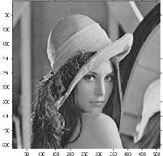
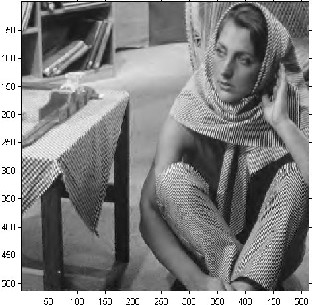
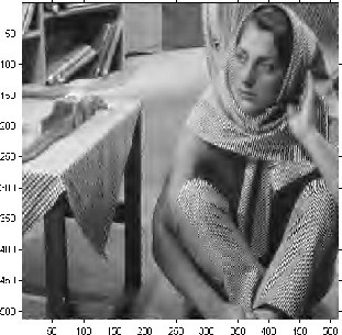
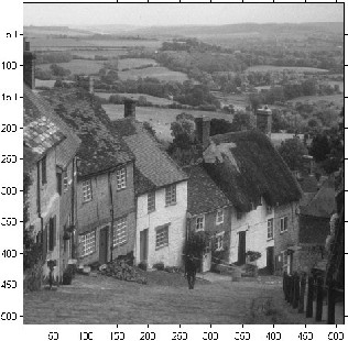
The NMEZW approach has tested on the three standard test grayscale images (Lena, Barbara and Goldhill) of
512‖×512‖ image size. The images are decomposed using the biorthogonal wavelet of type ―bior4.4‖, images are decomposed into five levels [16], [17], [18], [19].
IJSER © 2013 http://www.ijser.org
INTERNATIONAL JOURNAL OF SCIENTIFIC & ENGINEERING RESEARCH, VOLUME 4, ISSUE 9, SEPTEMBER-2013
ISSN 2229-5518
The following the metrics used in NMEZW. The metrics are shown below [10], [11], [12]:
Compression Ratio:
The NMEZW Codec is built and implemented using Matlab R(2011a) 64-bit application, implemented on using windows 7 ultimate operating system, working on hp pavilion dv6 Notebook PC, Intel Core i7 CPU of speed 2.00GHz for each processor.
The processing speed rate for the new NMEZW is
CR(bpp)
![]()
Number of
Coded
Bits
acceptable and the compression output is improved for
Number of
Initial Bits
... (4)
medium and high rates.
Mean Square Error:
N M
TABLE 4
Results of Different Algorithms Applied to Three Test Grayscale Images
(Lena, Barbara and Goldhill)
MSE
![]()
1
(xi
y j )
N M
i1
j 1
![]()
... (5)
Peak Signal to Noise Ratio:
(255)2
PSNR (dB) 10 log10
![]()
MSE
... (6)
Table 3 illustrates the compression results obtained of three test images (Lena, Barbara, Goldhill).
TABLE 3
Test Results for Lena, Barbara and Goldhill Grayscale Images
![]()
Table 4 shows a comparison among NMEZW and Different algorithms results of Lena, Barbara and Goldhill 512‖x512‖ grayscale test images.
In MEZW algorithm, the entropy of the tested grayscale images is redistributed on six types of symbols instead of four in EZW. This causes the total number of code symbols to be significantly reduced. However the entropy of the resulted symbols is changed, which solved in MEZW by regrouping the Dominant and the Subordinate symbols in new symbols. The same regrouping principle is used in the new proposed NMEZW algorithm but with redistributing the total Entropy on eight types of dominant symbols instead of six; which makes the total number of symbols reduced before being regrouped. The subordinate bit symbols are regrouped in new
8-bit size symbols just similarly to the regrouping used in
MEZW.
IJSER © 2013 http://www.ijser.org
INTERNATIONAL JOURNAL OF SCIENTIFIC & ENGINEERING RESEARCH, VOLUME 4, ISSUE 9, SEPTEMBER-2013
ISSN 2229-5518
The NMEZW Codec is built and implemented using Matlab R(2011a) 64-bit application, using windows 7 ultimate operating system, working on hp pavilion dv6 Notebook PC, Intel Core i7 CPU of speed 2.00GHz for each processor.
The processing speed rate for the new NMEZW is high for the built solution; the compression output is improved for medium and high compression rates.


![]()
![]()
![]()
IJSER !b) 2013
INTERNATIONAL JOURNAL OF SCIENTIFIC & ENGINEERING RESEARCH, VOLUME 4, ISSUE 9, SEPTEMBER-2013
ISSN 2229-5518
APPENDIX: RESULTED TEST IMAGES
Lena 512x512 grayscale image: a) Original image. b) Reconstructed image with CR (bpp) = 1.09, PSNR = 39.43 dB. c) Reconstructed image with
CR (bpp) = 0.50, PSNR=37.54 dB. d) Reconstructed image with CR (bpp) =0.25, PSNR=35.52 dB


IJ(a)

SER(b)
(c) (d)
IJSER © 2013 http://www.ijser.org
INTERNATIONAL JOURNAL OF SCIENTIFIC & ENGINEERING RESEARCH, VOLUME 4, ISSUE 9, SEPTEMBER-2013
ISSN 2229-5518
Barbara 512x512 grayscale image: a) Original image. b) Reconstructed image with CR (bpp) = 1.01, PSNR = 35.73 dB. c) Reconstructed image with
CR (bpp) = 0.51, PSNR=32.07 dB. d) Reconstructed image with CR (bpp) =0.22, PSNR=31.61 dB


IJ(a)
SER(b)
(c) (d)
IJSER © 2013 http://www.ijser.org
INTERNATIONAL JOURNAL OF SCIENTIFIC & ENGINEERING RESEARCH, VOLUME 4, ISSUE 9, SEPTEMBER-2013
ISSN 2229-5518
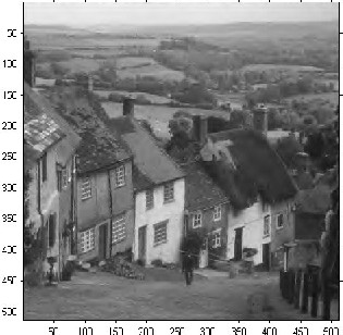
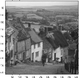
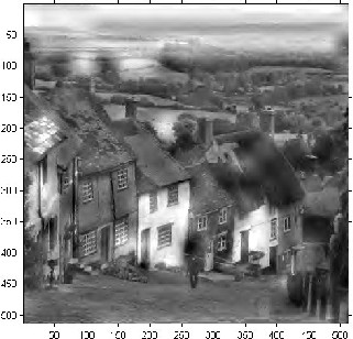
Goldhill 512x512 grayscale image: a) Original image. b) Reconstructed image with CR (bpp) = 0.94, PSNR = 37.13 dB. c) Reconstructed image with
CR (bpp) = 0.37, PSNR=28.81 dB. d) Reconstructed image with CR (bpp) =0.31, PSNR=28.30 dB
IJ(a)
SER(b)
(c) (d)
IJSER © 2013 http://www.ijser.org
INTERNATIONAL JOURNAL OF SCIENTIFIC & ENGINEERING RESEARCH, VOLUME 4, ISSUE 9, SEPTEMBER-2013
ISSN 2229-5518
REFERENCES
[1] Taubman, D. & Marcellin, M., "JPEG2000 Image Compression Fundamentals, Standards and Practice", Kluwer Academic Publishers, 2002-pages5, 306.
[2] Shapiro J.M. (1993), "Embedded image coding using zerotrees of wavelet coefficients", P IEEE Trans. Signal Proc., Vol. 41, No. 12, pp. 3445–3462.
[3] HU, Y. & et al., ―Embedded Wavelet Image Compression Algorithm Based On Full Zerotree", IJCSES International Journal of Computer Sciences and Engineering Systems, ISSN 0973-4406. 2007.
[4] Janaki, R. & Tamilarasi, A., "Still Image Compression by Combining EZW Encoding with Huffman Encode", International Journal of Computer Applications, Volume
13– No.7, 2011.
[5] Shi, Y. & Sun, H., "Image and Video Compression for
Multimedia Engineering, Fundamentals, Algorithms and
Standards, 2nd edition‖, CRC press, 2007, pages 216 to 228. [6] Woods, J.,"Multidimensional Signal, Image, and Video Processing and Coding Second Edition", Elsevier, 2012,
pages 363, 364.
[7] Acharya,T. & Tsai,P., "JPEG2000 Standard for Image Compression ,Concepts, Algorithms and VLSI Architectures", WI Leyinter Science, 2004,Pages 149.
[8] Goswami, J. & Chan, A., ―Fundamentals of Wavelets, Theory, Algorithm and Applications‖, 2nd Edition, Wiley,
2011, pages 41 to 69, 153, 273 to 294.
[10] Ouafi, A. & et al., ―A New Approach Based on Shapiro‘s Embedded Zerotree Wavelet (EZW) Algorithm for Image Compression", Asian Journal of Information Technology,
2006.
[11] Ouafi, A. & et al., "Color Image Coding by Modified
Embedded Zerotree Wavelet (EZW) Algorithm", IEEE,
2006.
[12] Ouafi, A. & et al., ―A Modified Embedded Zerotree Wavelet (MEZW) Algorithm for Image Compression", IEEE,Springer, 2008.
[13] Salomon, D.," Data Compression - The Complete Reference,
4th Edition", Springer, 2007, pages 626 to 630.
[14] Bovik, A., "The Essential Guide to Image Processing", Elsevier, 2009, pages 71 to 92.
[16] Daubechies, I. (1992), Ten lectures on wavelets, CBMS-NSF
conference series in applied mathematics. SIAM Ed.
[17] Mallat, S. (1989), "A theory for multiresolution signal decomposition: the wavelet representation," IEEE Pattern Anal. and Machine Intell., vol. 11, no. 7, pp. 674–693.
[18] Meyer, Y. (1990), Ondelettes et opérateurs, Tome 1, Hermann Ed. (English translation: Wavelets and operators, Cambridge Univ. Press. 1993.
[19] Said A., W.A. Pearlman (1996), "A new, fast, and efficient image codec based on set partitioning in hierarchical trees," IEEE Trans. on Circuits and Systems for Video Technology, Vol. 6, No. 3, pp. 243–250.
[9] Edwards, T., "Discrete wavelet Transforms, Theory & Implementation‖, Stanford University, September 1991, Draft #2, June 4, 1992.
IJSER © 2013 http://www.ijser.org