International Journal of Scientific & Engineering Research, Volume 5, Issue 5, May-2014 497
ISSN 2229-5518
A New Conformal Conical Phased Array
Antenna for Surveillance Radars
Hadia El-Henawy, Esmat Abdoul-Fattah, Magdy Gamal Electrical Engineering Department, Faculty of Engineering, Ain Shams University, Egypt
Magdy_Gaamal@yahoo.com
Mohamed Attala*, and Alaa S. Hafez
Electrical Engineering Department, Faculty of Engineering,
Alexandria University
alaahafez@ieee.org
Abstract—In this paper a new conformal array antenna of conical structure has been proposed. A conical phased array antenna can steer the radar beam electronically in both azimuth and elevation to cover a hemi-sphere mesh surrounding the radar antenna. Beam steering can be accomplished either continuously or discretely at definite directions. The proposed technique not only overcomes the limitations of mechanical steering systems and surveillance radar dead cone but also improves the radar tracking capability. Moreover, it is suitable to be used in MIMO radars and enemy deception systems. Element weights of the conical phased array antenna are used four famous window functions known as, Chebychev, Hamming, Hanning, and Kaiser window. The windowing process improves the beam pattern peak side lobe level (PSLL) while maintaining a narrow beam width. A high resolution phase shifter and adaptive attenuator have been used for each element to acquire both the desired phase and the weight for conical array beam pattern. Beam pattern is simulated and tested using a Matlab Program.
TABLE OF CONTENTS
1. INTRODUCTION……………………………… 1
2. THEORY OF CONICAL ARRAY ANTENNA........ 1
3. SIMULATION PROCESS ................................... 2
4. RESULTS ........................................................ 4
5. SUMMARY ...................................................... 6
REFERENCES ...................................................... 6
BIOGRAPHY ........................................................ 7
1. INTRODUCTION
A conformal antenna is one which adapts to a specific shape. The main goal is to design an antenna which can be integrated with the structure and does not produce an extra drag. In the past, three linear array antennas were used in many systems, such as cellular phone base stations. Each linear array covers 120 degrees. Development in coverage angle was achieved to reach 140 degrees with over lapping coverage zones [1]. Unfortunately, this causes more complexity in signal processing and feeding networks. So, the conformal phased array antenna appears to be the suitable methodology for a completely spherical covering zone with simple feeding networks. In the early development of conformal phase array antennas, a limited scanning angle up to ±50 degrees was achieved [2]. On the other hand, a conformal array antenna with omnidirectional beam pattern can cover a complete spherical zone [3]. An omnidirectional conformal antenna can be used in local broadcastings or weather radars but is not suitable for direction finding wireless systems. Currently conformal array antennas using switched Butler Matrix or switched serial networks were used as directive antennas in direction
finding systems [4-5]. The main drawback of using switched conformal array antennas is that they provide a switched beam pattern. Switched beam pattern does not introduce a satisfactory degree of continuous scanning, and it introduces a relatively small gain of few decibels, which is not suitable in radar application. Therefore, digital feeding networks using digital phase shifters and adaptive attenuators should be used [6]. Digital phase shifters play the main role of steering the antenna beam pattern over a spherical coverage zone. Adaptive attenuators are used to control the excitation of elements. Uniform excitation or distribution for conformal array antenna elements gives poor parameters such as high peak side lobe level [7]. So conformal array antenna excitations, dimensions, or number of elements should be optimized to get better performance. Optimization processes were applied to distribution of elements over antenna curved surface using method of moment and spectral domain approach [8]. These optimization processes give a better performance through the simulation results. A further optimization for location of elements over the conformal array surface was achieved to minimize the beam pattern side lobe level using particle swarm optimization [9]. Optimizing approaches based on the G.A have been used over a number of elements that form the circular array antenna to get lower side lobe level [10]. Also the new proposed conformal phased array antenna is optimized using G.A to get optimum element weights for minimum peak side lobe level while maintaining narrow half power beam width. Elements are distributed on a cone surface having distance greater than the half wave length to overcome mutual coupling between different elements [11].
IJSER © 2014 http://www.ijser.org
International Journal of Scientific & Engineering Research, Volume 5, Issue 5, May-2014 498
ISSN 2229-5518
2. THEORY OF CONICAL ARRAY ANTENNA
Figure 1 shows the conical array antenna structure. A circular array is the building block of conical array. Repetitive circular sub-arrays above each other with linearly descending diameters can form a conical array. N circular sub-arrays with each having M elements at the circle perimeter form a conical array with NM elements. The nmth element has wnm weight and βnm phase shift. L is the total cone length while θo is the half cone angle. Inclination distance between two successive circular arrays is
𝐿
𝑐𝑜𝑠𝛼𝑚 = 𝑎�𝑚 ʘ𝑎�𝑟 = �𝑠𝑖𝑛𝜃°𝑐𝑜𝑠∅𝑚 𝚤 + 𝑠𝑖𝑛𝜃° 𝑠𝑖𝑛∅𝑚 𝚥 −
𝑐𝑜𝑠𝜃° 𝑘� �ʘ�𝑠𝑖𝑛𝜃𝑐𝑜𝑠∅𝚤 + 𝑠𝑖𝑛𝜃𝑠𝑖𝑛∅𝚥 + 𝑐𝑜𝑠𝜃𝑘�� =
𝑠𝑖𝑛𝜃𝑠𝑖𝑛𝜃° cos(∅ − ∅𝑚 ) − 𝑐𝑜𝑠𝜃𝑐𝑜𝑠𝜃° (6)
The maximum of AF occurs at:
𝑛𝑘𝑑𝑐𝑜𝑠𝛼𝑚 + 𝛽𝑛,𝑚 = 0 (7)
𝛽𝑛,𝑚 = −𝑛𝑘𝑑𝑐𝑜𝑠𝛼𝑚 = −𝑛𝑘𝑑(𝑠𝑖𝑛𝜃𝑖 𝑠𝑖𝑛𝜃° 𝑐𝑜𝑠(∅𝑖 −
∅𝑚 ) − 𝑐𝑜𝑠𝜃𝑖 𝑐𝑜𝑠∅𝑚 ) (8)
𝑑 =
𝑁𝑐𝑜𝑠𝜃𝑜

(1)
Where𝜃𝑖 , ∅𝑖 are the elevation and azimuth angles of the
Observing the electromagnetic field at the cone tip from a
target oriented at a general point with spherical coordinates (r, θ, ϕ), due to the spatial distribution of elements, the array factor can be realized as
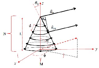
Figure 1- Conical Array Antenna.
𝐴𝐹(𝜃, ∅) = 𝑤1,1 𝑒𝑗�𝑘𝑑𝑐𝑜𝑠𝛼1+𝛽1,1� + 𝑤2,1 𝑒𝑗�2𝑘𝑑𝑐𝑜𝑠𝛼1+𝛽2,1� +
⋯ ⋯ ⋯ + 𝑤𝑁,1 𝑒𝑗�𝑁𝑘𝑑𝑐𝑜𝑠𝛼1 +𝛽𝑁,1� + 𝑤1,2 𝑒𝑗�𝑘𝑑𝑐𝑜𝑠𝛼2 +𝛽1,2� +
main lobe, respectively. Using the above formula, the phase
shift of the nmth element can be realized to steer the beam through a hemi-sphere scanning cell. The weight wnm may be uniform or may be in any form according to the designer’s needs. Weights are optimized to a obtain beam pattern with minimum peak side lobe level.
3. SIMULATION PROCESS
The simulation is done using Matlab program environment, Selecting the cone dimensions as L=10λ,θo =
38.3° and N=M=12 leads to smin = 0.682 λ, which is suitable
for mutual coupling avoidance. Phase shifters can adapt the
phase of each element. So the beam can be steered over a hemi-sphere coverage cell with 70o in elevation and 360o in azimuth. Higher resolution in phase shift selecting for each element leads to higher resolution in beam steering. Scanning rate for these types of antenna depends on the switching rate of phase shifters which can steer up to two degrees at 10 μsec. Thus, the beam can steer over the whole hemi-sphere coverage cell at 81 msec, i.e. more than 740 revolutions per min [13-14]. Antenna gain ‘G’ can be calculated as [15-16]:
⋯ ⋯ ⋯ + 𝑤𝑁,𝑀 𝑒𝑗�𝑁𝑘𝑑𝑐𝑜𝑠𝛼𝑀 +𝛽𝑁,𝑀� (2)

𝐺 = 4𝜋
𝜃1 𝜃2
(13)
𝑀 𝑁
𝐴𝐹(𝜃, ∅) = � � 𝑤𝑛,𝑚 𝑒𝑗�𝑛𝑘𝑑𝑐𝑜𝑠𝛼𝑚 +𝛽𝑛,𝑚�
𝑚=1 𝑛=1
1 ≤ 𝑛 ≤ 𝑁, 1 ≤ 𝑚 ≤ 𝑀 (3)
where θ1 and θ2 are the HPBW in E-plane and H-plane, respectively. Element weights have been used Chebychev, Hamming, Hanning, and Kaiser window functions, to be below 6°, weights with an 11×12 element array and with
−3
where k = 2π/λ is the angular wave number, λ is the wave
weight precision less than 10
which can be practically
length, 𝛼𝑚 is the solid angle between target unitvector (𝑎�𝑟 )
and mth element unit vector (𝑎�𝑚 ) and wnm =1 for uniform
excitation.
𝑎�𝑟 = �𝑠𝑖𝑛𝜃𝑐𝑜𝑠∅𝚤 + 𝑠𝑖𝑛𝜃𝑠𝑖𝑛∅𝚥 + 𝑐𝑜𝑠𝜃 𝑘�� (4)
𝑎�𝑚 = �𝑠𝑖𝑛𝜃°𝑐𝑜𝑠∅𝑚 𝚤 + 𝑠𝑖𝑛𝜃°𝑠𝑖𝑛∅𝑚 𝚥 − 𝑐𝑜𝑠𝜃° 𝑘� � (5)
where ∅𝑚 =2πm/M is the angular position of mth element.
𝑐𝑜𝑠𝛼𝑚 is the dot product between the mentioned unit
vectors and can be found as:
implemented. Due to the asymmetrical shape of conical
array antenna in elevation, element weights have to be adapted during beam steering. Digital RF adaptive CMOS attenuator can be a suitable variable attenuator for controlling element weight [17]. It has a resolution up to -
30dB. Element weights are substituted then; code words of binary bits corresponding to the desired phase and amplitude are introduced to variable phase shifters and adaptive attenuators, respectively.
IJSER © 2014 http://www.ijser.org
International Journal of Scientific & Engineering Research, Volume 5, Issue 5, May-2014 499
ISSN 2229-5518
HPBW (o) | 30 | 6 | 6 |
Max Tilting Angle (o) | 84 | 90 | 90 |
Antenna Gain (dB) | 11.8 | 30.6 | 30.6 |
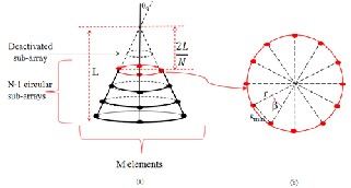
Figure 2- Array Antenna Structure
(a) Conical Array, (b) Circular Sub-array
Conical array antenna polarization does not depend only on single element polarization. Due to the curved surface of the array antenna, some elements would appear cross- polarized to others, causing high polarization loss factor (PLF). To overcome this problem, a simple solution is orientating the dipoles vertical axis (polar or polarization reference axis) to coincide with the cone axis. Otherwise, a polarization control device using a variable power divider VPD as in Figure 3 should be used for each element [18]. There are many possible element designs: crossed dipoles, crossed slots, and crossed notch elements .Orthogonal feeds can be used in many radiators such as patches, square and circular wave guides, and so on. With two-port elements, the radiated polarization can be set by feeding the two ports with proper amplitudes and phases. Feeding the two with equal amplitudes results in 45° slant polarization; any orientation can be obtained by a proper amplitude ratio. A variable power divider is a suitable circuit for realizing this.
4. SIMULATION RESULTS
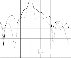
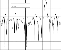
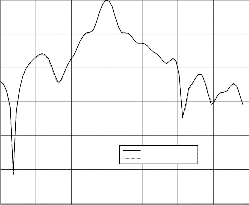
A conical array antenna is tested at four different cases: case (1), weighted by Chebychev window function, case (2), weighted by Hamming window function, case (3) weighted by Hanning window function; and case (4), weighted by Kaiser window function. Table 1 compares a conformal slotted waveguide array antenna and a conformal conical array antenna [19]. An improvement in PSLL with respect to conformal slotted wave guide array has been achieved by
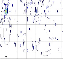
8 dB in addition to gain improvement by 18.8 dB.This improvement in gain occurs due to two factors. The first is the use of conical shape instead of cylindrical shape as in [19]. Conical shape improves the constructive interference at the desired direction and destructive interferences at the undesired directions. So a narrower beam width is achieved and hence a higher gain. The second factor is using 132 elements instead of 35 elements only as in [19].It is remarked that both the conical phased array antenna and helical antenna with linear-decreasing radii of its turns have the same shape. Figures 4 through 11 the array factor for the four window function compared with the uniform array. Figure 12 through 13 shows the 3D contour plot for the array factor at three desired directions. The proposed antenna has overcome the mechanical steering antenna systems limitations, disadvantages of tracking radars processing, and the dead cone of surveillance radar coverage zone. Conical array antenna permits this type of modern radar to operate in standalone conditions without the need of mutual covering. It also provides an efficient degree of passive deception for enemies, as it can be used at silent sentry radars.
0
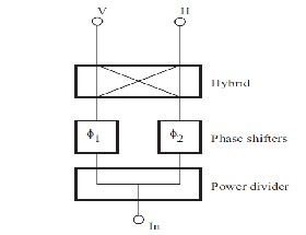
Figure 3- Variable Power Divider
Table 1. Comparison between types of conformal arrays
-10
-20
-30
-40
-50
-60
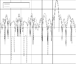
Uniform Array
Cebychev Window Array
-70
0 50 100 150 200 250 300 350
Azimuth Angle (0)
IJSER © 2014 http://www.ijser.org
International Journal of Scientific & Engineering Research, Volume 5, Issue 5, May-2014 500
ISSN 2229-5518
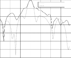
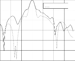
Figure 4- Azimuth array factor with Cebychev weighting
Figure 7- Elevation array factor with Hamming weighting
0 0
-10
Uniform Array
Chebychev Window Array
-10
Uniform Array
Hanning Window Array
-20
-20
-30
-30
-40
-50
-40
-60
-50
-70
0 10 20 30 40 50 60 70
Elevation Angle (o)
-60
0 50 100 150 200 250 300 350
Azimuth Angle (o)
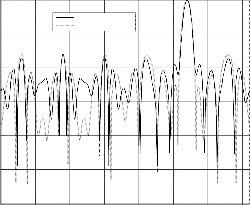
Figure 5- Elevation array factor with Cebychev weighting
Figure 8- Azimuth array factor with Hanning weighting
0 0
-10
Uniform Array
Hamming Window Array
-10
Uniform Array
Hanning Window Array
-20
-20
-30
-30
-40
-40
-50
-50
-60
0 50 100 150 200 250 300 350
Azimuth Angle (o)
-60
0 10 20 30 40 50 60 70
Elevation Angle (o)
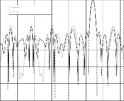
Figure 6- Azimuth array factor with Hamming weighting
Figure 9- Elevation array factor with Hanning weighting
0 0
-10
-10
Uniform Array
Kaiser Window Array
-20
-20
-30
-30
-40
-40
-50
Uniform Array
Hamming Window Array
-50
-60
0 10 20 30 40 50 60 70
Elevation Angle (o)
-60
0 50 100 150 200 250 300 350
Azimuth angle (o)
IJSER © 2014 http://www.ijser.org
International Journal of Scientific & Engineering Research, Volume 5, Issue 5, May-2014 501
ISSN 2229-5518
Figure 10- Azimuth array factor with Kaiser weighting
0
-10
-20
-30
-40
-50
Uniform Array
Kaiser Window Array
60
50
40
30
20
10
0
0 50 100 150 200 250 300 350
Azimuth Angle (o)

1
0.9
0.8
0.7
0.6
0.5
0.4
0.3
0.2
0.1
-60
0 10 20 30 40 50 60 70
Elevation angle (o)
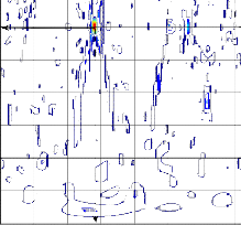
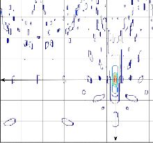
Figure 13- 3D Contour plot for the AF at desired direction
Figure 11- Elevation array factor with Kaiser weighting

1

1
60 0.9
0.8
50
0.7
40
0.6
30 0.5
0.4
20
0.3
10
0.2
60
50
40
30
20
10
0
0 50 100 150 200 250 300 350
Azimuth Angle (o)
0.9
0.8
0.7
0.6
0.5
0.4
0.3
0.2
0.1
0
0 50 100 150 200 250 300 350
Azimuth Angle (o)
0.1
Figure 14- 3D Contour plot for the AF at desired direction
Figure 12- 3D Contour plot for the AF at desired direction
5. SUMMARY
A complete analysis and design for conical array antenna are introduced as an application for modern radar using a high resolution phase shifter. Antenna dimensions and parameters are optimized using a genetic algorithm to obtain minimum peak side lobe level while maintaining a relatively narrow beam width. Physical phenomena such as mutual coupling between elements and polarization loss have been taken in consideration. The designed antenna has been simulated and tested using a Matlab program, with the aid of its graphical capability. The proposed conformal array antenna achieves PSLL of -19.08 dB, MSLL of -22.7 dB and antenna gain of 30 dB. The results are compared with slotted wave guide conformal array antenna results. An improvement in PSLL by 8 dB takes place in addition to gain improvement by 18.8 dB. The proposed antenna has overcome the mechanical steering antenna systems
IJSER © 2014 http://www.ijser.org
International Journal of Scientific & Engineering Research, Volume 5, Issue 5, May-2014 502
ISSN 2229-5518
limitations, disadvantages of tracking radars processing, and the dead cone of surveillance radar coverage zone. Conical array antenna permits this type of modern radar to operate in standalone conditions without the need of mutual covering. It also provides an efficient degree of passive deception for enemies, as it can be used at silent sentry radars.
REFERENCES
[1] Noordin N.H., Haridas N.,El-Rayis A.O.,Erdogan A.T.,Arslan T., “Antenna Array with Wide Angle Scanning Properties”, Antennas and Propagation (EUCAP), 2012 6th European Conference, Conference Publications, Edinburgh, UK, March 2012.
[2] Cella T., Askeland S.A.,Hjelmstad J., “Design and Simulation of Conformal Array Structure for Traffic Surveillance
Concept”, Wireless and Microwave Technology Conference (WAMICON), 2012 IEEE 13th Annual, Conference Publications, Trondheim, Norway, April 2012.
[3] Dan Sun, Wenbin Dou, Xuequan Yan, “A Broadband Phased Array System with Cylindrical Conformal Antenna”, IEEE Microwave and Millimeter Wave Technology (ICMMT),
2012 International Conference, Conference Publications, China, May 2012.
[4] Madany Y.M., Elkamchouchi H.M.,Salama A.A., “Design and Analysis of Optimum Miniaturized Conformal Smart Antenna System Using 1×8 Switched Butler Matrix for Wireless Applications”, IEEE Microwave and Millimeter Wave Technology (ICMMT), 2012 International Conference, Conference Publications, May 2012.
[5] Blersch T., Hesselbarth J., “A Switched Beam Antenna for
Hemispherical Coverage”, IEEE Smart Antennas (WSA),
2012 International ITG Workshop, Conference Publications, Stuttgart, Germany, March 2012.
[6] Ping Wang, Guangjun Wen, Yuanhua Sun, Haobing Zhang, “Design of Wideband Conformal End-fire Antenna Array on a Large Conducting Cylinder”, Antennas and Propagation (APCAP), 2012 IEEE Asia-Pacific Conference, Conference Publications, Chengdu, China, Aug. 2012.
[7] Chorfi H., NedilM.,BenMabrouk I.,Denidni T.A.,Talbi L., “Design of a 60 GHz Dielectric Resonator Antenna Array
Mounted on a Conformal Structure”, Antennas and
Propagation Society International Symposium (APSURSI),
2012 IEEE, Conference Publications, July 2012.
[8] Mandric V., Rupcic S., Zagar D., “Optimization of the
Spherical Antenna Arrays”, IEEE ELMAR, 2012
Proceedings, Conference Publications, Osijek, Croatia, Sept.
2012.
[9] Yang K., Zhao Z.,Ouyang J., Nie Z., Liu Q.H., “Optimisation
Method on Conformal Array Element Positions for Low Side Lobe Pattern Synthesis”, IEEE Microwaves, Antennas & Propagation, IET, Volume 6, Issue 6, Chengdu, China, April
2012.
[10] YuguanHou, JianKang,YiyingShen,ChengyuHou, “A Thinning Method of Conformal Non-Concentric Circular Array Using Genetic Algorithm”, IEEE, Antennas, Propagation & EM Theory (ISAPE), 2012 10th International Symposium, Conference Publications, Harbin, China, Oct.
2012
[11] Dan Sun, Wenbin Dou, Xuequan Yan, “A Broadband Phased Array System with Cylindrical Conformal Antenna”, IEEE Microwave and Millimeter Wave Technology (ICMMT),
2012 International Conference, Conference Publications, China, May 2012.
[12] Hu Hang, Lei Lili, Hu Yi, Wu Qun, Sub-array weighting method for side lobe suppression of difference pattern based on genetic algorithm, IEEE Antennas and Propagation
Society International Symposium, AP-S 2008, July 2008.
[13] Ahmed KhairyAboul-Seoud, Ahmed Hamed, and Alaa El-Din Sayed Hafez, Wideband Tunable MEMS Phase Shifters for Radar Phased Array Antenna, 29th NATIONAL RADIO SCIENCE CONFERENCE (NRSC 2012), Faculty of Engineering, Cairo University, Egypt, April 2012.
[14] Internet Site:http://www.microwaves101.com/encyc- lopedia/phaseshifters_switchedline, last visited, Dec. 2012.
[15] Constantine A. Balanis, Antenna Theory, Analysis and, Design, John Wiley & Sons, Inc.
[16] John S. Seybold, Ph.D, Introduction to RF propagation, John
Wiley & Sons, Inc.2005.
[17] Yan-Yu Huang, Wangmyong Woo, Youngchang Yoon, Chang-Ho Lee, Highly Linear RF CMOS Variable Attenuators with Adaptive Body Biasing, IEEE Solid-State Circuits Society. May 2011.
[18] Lars Josefsson, and Patrik Persson, Conformal Antenna
Theory and Design, IEEE Antennas and Propagation
Society, Sponsor.
[19] Yuan-Yun Liu, Min Guo, Shun-Shi Zhong, “Conformal slotted waveguide array antenna”, Antenna Technology (iWAT), 2012 IEEE International Workshop, Conference Publications, Shanghai, China, Jan 2012.
BIOGRAPHIES

Magdy Gamal is an Post Graduate Studen (Ph.D.), Ain Shams University, Cairo, Egypt. He holds B.Sc. in Electronics and Communications from Faculty of Engineering, Alexandria University, M.Sc. in Electrical Engineering from Faculty of Engineering,
Alexandria University. He received many technical courses in electronic engineering design and Implementation.

Mohammed El-Amir Attalah is an affiliate instructor in Faulty of Engineering, Alexandria University, Alexandria, Egypt. He holds B.Sc. in Electronics and Communications from Faculty of Engineering, Alexandria University, He also holds M.Sc. and Ph.D. in Electrical
Engineering from Faculty of Engineering, Alexandria University. He received many technical courses in Electronic system design and Implementation, work as System Engineer for more than 10 years, teach up to 25 undergraduate subjects, supervising more than 15 thesis, publish more than 50 papers in different international conferences and journals.
IJSER © 2014 http://www.ijser.org
International Journal of Scientific & Engineering Research, Volume 5, Issue 5, May-2014 503
ISSN 2229-5518

Alaa El-Din Sayed Hafez is an affiliate instructor in Faulty of Engineering, Alexandria University, Alexandria, Egypt. He holds B.Sc. in Electronics and Communications from Faculty of Engineering, Alexandria University, M.Sc.
in Electronics and Communication from
Arab Academy for Science and Technology and Maritime Transport, Alexandria. He also holds M.Sc. and Ph.D. in Electrical Engineering from Faculty of Engineering, Alexandria University. He received many technical courses in Surveillance Radar design and Implementation, work as Radar System Engineer for more than 5 years, teach up to
20 undergraduate subjects, supervising more than 12 thesis, publish more than 40 papers in different international conferences and journals.
IJSER © 2014 http://www.ijser.org